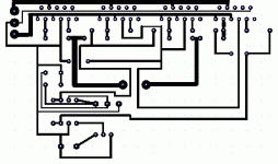
Hi, I just thought that you should probably know that your board may need some small alterartions, as if you do go for this design, you will be getting peak currents of over five amps flowing in the circuit, and at the momnet the power tracks are just way too thin to handle that. So, you may want to beef up the tracks you are using for the power lines, output and ground so that they can handle the current you want to put down them. (I would sujest about 0.1 to 0.15 inch for 1 ounce copper board).
As far as the resistors go, for all apart from the output ones, just use standard 1% metal films that you can pick up from radio shack or something seen as this is your first attempt, as you can always change them out at a later date. And as for the output resistors, you will need at least 5W or so rating on them, so I would just go for 5% wire wound ones of rnow too.
As far as the resistors go, for all apart from the output ones, just use standard 1% metal films that you can pick up from radio shack or something seen as this is your first attempt, as you can always change them out at a later date. And as for the output resistors, you will need at least 5W or so rating on them, so I would just go for 5% wire wound ones of rnow too.
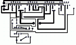
Heres the revised pcb. I did the original in a trial software program, so it wouldn't let me save and I had to use print screen and paint to save it. So, I had to edit it in paint. Not all the connections are done. Does the + input need a thick wire connecting to ground? I couldn't fit a larger one than I have now. Is the new thickness of the + - and speaker wires thick enough (gnd isn't done and nor is the connections to the otuput resistors)?
Attachments
What you have done is a fair improvement, but it looks like you still have the output resistors as 1/4W sizes, and if you use these you will probably blow them up if you turn the volume up much, so they realy do need to be replaced with higher power ones.
If you can wait for the PCB, I am planing on designing something similar soon (I just changed from using eagle, to Protell, so I am trying to re-learn how to draw a scheematic, then convert it to a PCB design), however, I was going to go for a design with six chips per channel (Bridged, with three chips in parallel so to give better drive below 8 ohm loads). I was also, going to try and put a little more flexibility into the board, so that, it can be used in defferent configurations (two seperate banks to three parallel chips. three lots of two parrallel chips, or six seperate amplifiers.
But as I am comming to the end of term at university at the momnet, I have quite a bit of work on till next week, so I probably won't have a final design until some point near the middle of next week.
Well, I would like to stick with what I have. I have finished the trace size increases. You did say something about driving lower than 8-ohm speakers and using 6 chips. My speaker is a 4-ohm, will it not work well? Also, I wouldn't use 1/4W resistors. I would use larger ones but just mount them sticking up off the board. I also don't like double sided. I tried one before, on a headphone amp, and yes it worked, but half the parts I had to mount like surface mount because the drilled hole went through two traces.
Are you saying that something isn't good about this design?
Are you saying that something isn't good about this design?
Attachments
Hi, the thing about the chips being able to drive a four ohm load can be a bit confusing at times. Basicly if you have it so that you are getting about 50W into an 8 ohm load, the power will not double into a four ohm load, but instead you will get about 60-70W. The same goes for a bridge/paralel configuration with four chips; you will get about 200W (at a fair maximum) into an eight ohm load, but probably only 300W into a four ohm load not the 400w you might be hoping for.
To try and get round this a little you can parallel more chips, so the apparnet load each chip will see is increased and they cna drive closer to their expected maximum rating without having the thermal or current limiting cut in. basiclay, it should get me an extra 50% increase or so in power at lower loads (say around 350-370W into a four ohm load).
But, the design that you have already chosen with the four chips will still happily power a four ohm load, so there is no real need to change it (300W is still about six time the amount of power I have inot my speakers at teh momnet, and I'm pretty sure it would fry them if I did try and run them a 300W).
soundNERD said:Yes, I know I didn't have room to attach the mute pin. It won't have a mute switch, so all I do is tie the pins together and connect to ground through 1 resistor, right? Or do I need a resistor for each output?
You must connect mute pins to -V and draw 0,5mA from each mute pin to switch mute off.
I think it would be best to use individual resistors for each chip, in case the voltage at the pin on each chip isn't quite the same.
As far as a transformer goes, if you want to be able to run this happily into a four ohm load, I would sujest going for a 25 - 0 - 25, 600VA asa a minimum per channel, or perhaps a 1kVA if you are going to be running two from the same transformer.
As far as a transformer goes, if you want to be able to run this happily into a four ohm load, I would sujest going for a 25 - 0 - 25, 600VA asa a minimum per channel, or perhaps a 1kVA if you are going to be running two from the same transformer.
Well, there are quite a few out there and I guess the ones that would be any good for me would be less so for you as the cost of shipping from one side of the atlantic to the other for such heavy items won't be cheep. However, I have heard a lot of people in the US and canada talking about Piltron and Victoria Magnetics as being two of the more DIY friendly compnaies to deal with, but there is always the option of looking up which standard models someone like digikey stock and seeing if you can use a one of those.
soundNERD said:OK, I am finally getting ready to build it.
I noticed that the feedback resistors are 220K. Normally I use somewhere around 30K. Wouldn't the 220K give it too high of gain?
Thanks, Mike
It depend what is value of the other feedback resistor, if it's 10k and amp is inverting, you are going to get gain of 22 (26.8dB), witn NI gain is 23 (27.3dB). that's with 10k, with 1k for example, it will be Inv=220 or NI=221
- Status
- This old topic is closed. If you want to reopen this topic, contact a moderator using the "Report Post" button.
- Home
- Amplifiers
- Chip Amps
- Chainclones - how do they sound

