I'm looking for a line-level buffer stage to precede a volume pot. The criteria are that it a) needs to run from the PA main rails; b) capable of driving a 1k pot; b) reasonably high input impedance; c) DC coupled input and output, with very low offset to minimise any DC across the pot track ends.
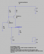
I've come up with the circuit below, which is reasonably simple and meets my requirements. Any suggestions before I commit to layout and assembly?
Edit; see post #11 for information about modern op amps capable of driving a 1k pot to line levels.
I've come up with the circuit below, which is reasonably simple and meets my requirements. Any suggestions before I commit to layout and assembly?
Edit; see post #11 for information about modern op amps capable of driving a 1k pot to line levels.
Attachments
Last edited:
Hi,
the circuit isn´t as simple as it looks ... it requires three current sources.
If its just for buffering purposes why not stick to the diamond structure?
There´s no need to build a differential gain stage, forced down to a gain of 0dB.
Also You can get the supply down to more reasonable values with simple capacitance multiplier stages with their Vout set by base resistor dividers ... with the advantage of clean supply rails for the buffer.
In that case You could use integrated buffers again, like LME49600 or BUF634.
jauu
Calvin
Hi Calvin
I had considered a diamond buffer; it certainly has the benefit of simplicity; however, good measured performance depends on close matching between the PNP and NPN devices, which is difficult in practice and hence a reason why I favour single-ended topologies. The other reason is that I find they usually sound better too.
The cap multiplier is a great suggestion and I'll have a look into those buffer ICs also.
Thanks!
Hi Hugh
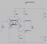
My first thought was a simple SE CFP using a pair of BJT devices, resistor loaded. The issue here is that with the input grounded, the output is at about 1VBE, which is a lot to put across the pot track - scratchy noise when rotating and all that. The obvious solution is a 220uF lytic at the output; however, its bulky and my friend insists that he can hear these in the signal path. A better alternative might be to AC couple the input with a small film cap and bias the input so the output is nulled.
NB: the model shows 40V rails, which are actually 55V PA rails regulated down to a reduced voltage.
Cheers
Christian
Attachments
Hi,
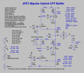
You can omit with the offset problem when using a JFET-bipolar Hybrid-CFP buffer.
See examples on my website which use easy to source N-channel JFETs only.
You can simplify the Calvin buffer by omitting with the cascoding JFETs (only 4 transistors) and the parts which modulate the ´lower´ ccs at the cost of increased THD at ower load impedances.
It´s also easy to null out the output offset.
You need of course reduce the supply rails to sufficiently lower values (2 more transistors).
jauu
Calvin
Attachments
Last edited:
op amps really should be considered an option at the parts counts shown so far
monolithic op amps really should be considered an option at the parts counts shown so far - just add a pair of zener shunt regs and use almost any "audio" op amp that meets your fancy
certainly makes meeting the electical performance specs easier
and there are op amps that can run from most PA rails: LTC6090 @140 Vs_max is one
always amused when at this late date discrete is is still considered "simpler" or especially "superior" for audio line level applications
properly selected, applied op amps should be considered the defualt audio line level building block with only extremes of low noise input or I, V out requirements requiring discrete - and then the discretes can often be used in composit circuits with op amps
Last edited:
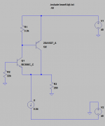
Hi Ranchu32, your circuit is a variant of the Schlotzaur'circuit, which some discovered in Douglas Self book "Small Signal Audio Design".
I tested this one with a 3 transistors current mirror which makes it very linear, less the -130 THD at 1 kHz, 4 Vrms. R4 and R102, 1 kOhm, resistors were introduced to see the effects of resistance in series with the inputs.
There may be a problem in your circuit, collector of Q2 being at almost the same voltage as it base. Having CFP input makes the circuit more noisy than single transistors but they could be with for high impedance sources.
I tested this one with a 3 transistors current mirror which makes it very linear, less the -130 THD at 1 kHz, 4 Vrms. R4 and R102, 1 kOhm, resistors were introduced to see the effects of resistance in series with the inputs.
An externally hosted image should be here but it was not working when we last tested it.
There may be a problem in your circuit, collector of Q2 being at almost the same voltage as it base. Having CFP input makes the circuit more noisy than single transistors but they could be with for high impedance sources.
Last edited:
monolithic op amps really should be considered an option at the parts counts shown so far - just add a pair of zener shunt regs and use almost any "audio" op amp that meets your fancy
certainly makes meeting the electical performance specs easier
and there are op amps that can run from most PA rails: LTC6090 @140 Vs_max is one
always amused when at this late date discrete is is still considered "simpler" or especially "superior" for audio line level applications
properly selected, applied op amps should be considered the defualt audio line level building block with only extremes of low noise input or I, V out requirements requiring discrete - and then the discretes can often be used in composit circuits with op amps
jcx, you make a fair point in relation to op amps for audio use. The way I see it the high voltage PA rails needs to be dropped as heat somewhere, and from that perspective it makes little difference whether hot regs are feeding cold op amps vs. cool regs feeding a hot discrete line buffer.
But a single, ordinary op amp section isn't going to be able to drive ~2Vrms into a 1k pot, so the solution is probably going to involve a discrete voltage follower inside the op amp's feedback loop, or several op amp sections in parallel. I built a buffer from four paralleled NE5532 sections configured as unity gain buffers driving a 1k pot and it worked extremely well, eliminating a faint hiss that was audible with my ear pressed to the tweeters. I accept that this low impedance design a la Self was in all likelihood incidental to other factors, namely improved power, ground and signal routing; nonetheless, I'm interested in pursuing this further.
But your suggested high voltage LT part has me scratching my head. Of the four suppliers that I use (RS, Farnell, Digikey & Mouser) only Digikey stock it, for the princely sum of A$10 ea. and only in a couple of decidedly non-DIY friendly packages - SOIC and TSSOP. I'm certain I could build something from discrete components at less cost and with less fiddling around.
Hi,
You can omit with the offset problem when using a JFET-bipolar Hybrid-CFP buffer.
See examples on my website which use easy to source N-channel JFETs only.
You can simplify the Calvin buffer by omitting with the cascoding JFETs (only 4 transistors) and the parts which modulate the ´lower´ ccs at the cost of increased THD at ower load impedances.
It´s also easy to null out the output offset.
You need of course reduce the supply rails to sufficiently lower values (2 more transistors).
jauu
Calvin
I played around with the stripped down model attached and it does look quite promising. The only fly in the ointment is that the output offset is determined by R1, which will need to be calibrated due to variations in different fet parameters. I really hate trimmers and given the choice, I'd much rather a Big Cap at the output, in which case I might as well use a couple of BJTs to build the CFP.
I know I could get around the trimmer with a servo, but that's a lot of extra unwanted complexity, not to mention the fact that an op amp doing servo duty could just as easily serve as the actual buffer, to jcx's point, and do away with all the other mess.
Hi Ranchu32, your circuit is a variant of the Schlotzaur'circuit, which some discovered in Douglas Self book "Small Signal Audio Design".
I tested this one with a 3 transistors current mirror which makes it very linear, less the -130 THD at 1 kHz, 4 Vrms. R4 and R102, 1 kOhm, resistors were introduced to see the effects of resistance in series with the inputs.
There may be a problem in your circuit, collector of Q2 being at almost the same voltage as it base. Having CFP input makes the circuit more noisy than single transistors but they could be with for high impedance sources.
Yes that's right, forr. I don't claim any originality and the basic circuit is probably an old one that Self described in his book. I think you might be right about Q2 and I noticed this to when I ran the simulation, which is one of the reasons why I posted here looking for confirmation. The situation improves when the resistors around the CFP inputs are reduced but this has the unfortunate consequence of increasing the output offset.
I did play around with a very similar circuit to the one you've posted but with a 2T current mirror. I thought the results were a little disappointing. I'll play around your circuit that has the more accurate mirror and heavy degen resistors and see where that leads.
The obvious question that really needs to be answered: how much offset is acceptable before the effects become audible when the pot is moved?
Attachments
please quit making up factually false objections to op amps
if you want to use discrete for fun/challenge thats fine
objecting to op amp performance on false grounds makes it hard for others to learn, make reasoned choices
perhaps you haven't looked at newer offerings - like since the mid '90s?
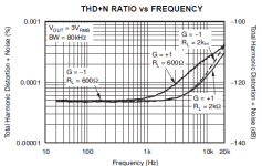
you don't have to look at many of the last few decades recommended "audio" op amps to find 600 Ohm drive plots to >6 Vrms with ppm distortion
paying even $10 for a modern high performance op amp in a one off hobby circuit is cheap compared to the time and effort in designing gathering discrete parts, layout...
again if your diy interest, real goal is a "junk box" discrete build thats fine - but don't pretend, claim to the larger community that its because modern op amps can't out perform
obviously the high V LTC part isn't exactly "line level" - just added to point out another dimension you objected to that is in fact covered by monolithic op amps
but SOIC is diy hand solderable - only the power pad heat sinking is the least bit challenging if needed at all in your application - and diy reflow is well developed too today
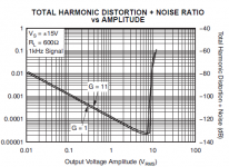
recent candidates I would consider: OPA827, OPA1642 distortion vs load plots:
if you want to use discrete for fun/challenge thats fine
objecting to op amp performance on false grounds makes it hard for others to learn, make reasoned choices
perhaps you haven't looked at newer offerings - like since the mid '90s?
jcx, you make a fair point in relation to op amps for audio use. The way I see it the high voltage PA rails needs to be dropped as heat somewhere, and from that perspective it makes little difference whether hot regs are feeding cold op amps vs. cool regs feeding a hot discrete line buffer.
But a single, ordinary op amp section isn't going to be able to drive ~2Vrms into a 1k pot, so the solution is probably going to involve a discrete voltage follower inside the op amp's feedback loop, or several op amp sections in parallel. I built a buffer from four paralleled NE5532 sections configured as unity gain buffers driving a 1k pot and it worked extremely well, eliminating a faint hiss that was audible with my ear pressed to the tweeters. I accept that this low impedance design a la Self was in all likelihood incidental to other factors, namely improved power, ground and signal routing; nonetheless, I'm interested in pursuing this further.
you don't have to look at many of the last few decades recommended "audio" op amps to find 600 Ohm drive plots to >6 Vrms with ppm distortion
is a strawman argument - yes you do have to choose the op amp for the application...single, ordinary op amp section isn't going to be able to drive...
paying even $10 for a modern high performance op amp in a one off hobby circuit is cheap compared to the time and effort in designing gathering discrete parts, layout...
again if your diy interest, real goal is a "junk box" discrete build thats fine - but don't pretend, claim to the larger community that its because modern op amps can't out perform
obviously the high V LTC part isn't exactly "line level" - just added to point out another dimension you objected to that is in fact covered by monolithic op amps
But your suggested high voltage LT part has me scratching my head. Of the four suppliers that I use (RS, Farnell, Digikey & Mouser) only Digikey stock it, for the princely sum of A$10 ea. and only in a couple of decidedly non-DIY friendly packages - SOIC and TSSOP. I'm certain I could build something from discrete components at less cost and with less fiddling around.
...
but SOIC is diy hand solderable - only the power pad heat sinking is the least bit challenging if needed at all in your application - and diy reflow is well developed too today
recent candidates I would consider: OPA827, OPA1642 distortion vs load plots:
Attachments
Last edited:
Why the angst jcx? I never said that op amps can't perform in this application and actually gave an example where I felt they performed "extremely well". So I wouldn't fret about others being turned off them based on my comments.
I'm not on some anti-opamp crusade as you seem to imply, but your strenuous protests make me wonder about your agenda.
My definition of an "ordinary" op amp is a through hole package that I can pick up from the local parts store, which in Oz is essentially the Jaycar chain. As far as I can tell the range is 1970's technology:
https://www.jaycar.com.au/products/active-components/integrated-circuits/linear/c/210B
I don't see your point. I don't put a $ value on my time because this is a hobby for me and if I didn't enjoy spending time researching, gathering discrete parts, etc. I wouldn't be interested in op amps either - I'd be straight down to the hi-fi store and out again with a PA and a pre-amp under each arm.
Thanks for those op amp suggestions, the specs are excellent and they're available from all the usual online sources, albeit in SOIC unfortunately. 2 and 3 legged SMT devices are no drama but the 6+ pin stuff gives me a lot of grief. I don't have a reflow oven in the workshop but its time to improve my hand soldering skills and equipment I think.
I'm not on some anti-opamp crusade as you seem to imply, but your strenuous protests make me wonder about your agenda.
My definition of an "ordinary" op amp is a through hole package that I can pick up from the local parts store, which in Oz is essentially the Jaycar chain. As far as I can tell the range is 1970's technology:
https://www.jaycar.com.au/products/active-components/integrated-circuits/linear/c/210B
paying even $10 for a modern high performance op amp in a one off hobby circuit is cheap compared to the time and effort in designing gathering discrete parts, layout...
I don't see your point. I don't put a $ value on my time because this is a hobby for me and if I didn't enjoy spending time researching, gathering discrete parts, etc. I wouldn't be interested in op amps either - I'd be straight down to the hi-fi store and out again with a PA and a pre-amp under each arm.
Thanks for those op amp suggestions, the specs are excellent and they're available from all the usual online sources, albeit in SOIC unfortunately. 2 and 3 legged SMT devices are no drama but the 6+ pin stuff gives me a lot of grief. I don't have a reflow oven in the workshop but its time to improve my hand soldering skills and equipment I think.
no problem with good fun, just with bad justifications
basically your specific claim and the rest of the thread's participants silent acceptance of "op amps can't do that" just happened to push a couple of my hot buttons
your 1st post included a start on a performance based specification for the circuit
got my hopes up, then appeared to degenerate into the "op amps bad, discrete always better" audiofool meme
you make claims about op amps that aren't true today, haven't been for a decade or two if you allow for intelligent selection of better op amps for the application
you do this by appeal to "op amps" "failings" re driving 1 kOhm loads in audio applications
then defend it, reveal the "strawman" assumption: "oh I didn't mean good op amps"
and everyone shows discrete circuits that could probably be beat on performance with the 30 year old design <$1 commodity op amps and a little added discrete circuitry that you dismissed – how many shown discrete buffers in this thread are really going to beat the 5534?
I expect pronouncements of what can and can't be done with a particular technology to be informed, reasonably up to date
for audio line level circuitry Self's 2010 "Small Signal Audio Design" and/or free resources for audio line level design, op amp capabilities: Walt Jung's "Op Amp Applications" history/handbook and Groner's excellent work Analog Circuit Design · Samuel Groner · Resources · IC OpAmps would be my minimum expectation
hand soldering SOIC-8 50 mil gull wing leads isn't that much of a challenge with a circuit board – only “dead bug” or perfboard builds are problematic without dip adapter or “surf board” transition parts
a selection of tips and solder sizes for the job helps, and of course past a certain age very good lighting, magnifying optics become near mandatory
Last edited:
Ranchu's circuit belongs to a family on which Self had written some pages in this book. The chapter ended with the words "Work in progress". A few persons here have built a Schlotzaur circuit, they have been impressed by the objective results. The topology can be a source of inspiration for power amp output stages.for audio line level circuitry Self's 2010 "Small Signal Audio Design"
Hi jcx
I've edited my post #1 to clear up any misunderstandings.
You expect a lot from a hobbyist asking questions on a DIY board. Of those books I have a copy of "Small Signal Audio Design", which contains a whole section dedicated to the sorts of discrete circuits discussed in this thread. The author provides measurements to back his claims and justifies their use over op amps in situations including when "best possible distortion performance is demanded" and "it would be necessary to provide a low voltage supply to run just one or two op amps".
Of the jfet op amps surveyed, all show dramatically increased distortion at high frequencies with heavy loads, apart from the expensive/specialised OPA627. None of the parts you mention were included.
It seems that Douglas Self has fallen into the same trap by not doing his research and/or forgetting to include these modern parts in his book. Kind of undermines your argument, wouldn't you agree?
Why can't you simply be upfront about the fact that you have an unusually good knowledge (by hobbyist standards at least) of modern op amp technology and would like to see these parts used more in audio circuits, because a part exists that will fulfil all the required criteria 99% of the time?
I've edited my post #1 to clear up any misunderstandings.
I expect pronouncements of what can and can't be done with a particular technology to be informed, reasonably up to date
for audio line level circuitry Self's 2010 "Small Signal Audio Design" and/or free resources for audio line level design, op amp capabilities: Walt Jung's "Op Amp Applications" history/handbook and Groner's excellent work Analog Circuit Design · Samuel Groner · Resources · IC OpAmps would be my minimum expectation
You expect a lot from a hobbyist asking questions on a DIY board. Of those books I have a copy of "Small Signal Audio Design", which contains a whole section dedicated to the sorts of discrete circuits discussed in this thread. The author provides measurements to back his claims and justifies their use over op amps in situations including when "best possible distortion performance is demanded" and "it would be necessary to provide a low voltage supply to run just one or two op amps".
Of the jfet op amps surveyed, all show dramatically increased distortion at high frequencies with heavy loads, apart from the expensive/specialised OPA627. None of the parts you mention were included.
It seems that Douglas Self has fallen into the same trap by not doing his research and/or forgetting to include these modern parts in his book. Kind of undermines your argument, wouldn't you agree?
Why can't you simply be upfront about the fact that you have an unusually good knowledge (by hobbyist standards at least) of modern op amp technology and would like to see these parts used more in audio circuits, because a part exists that will fulfil all the required criteria 99% of the time?
Back to the task at hand
I've done more analysis on the circuit at post #1 and don't believe it is really viable for the reason forr mentioned.
If we allow ourselves a big coupling cap at the output then almost anything is possible, but if we want to eliminate it, then the SE CFP buffers (2BJT or JFET/BJT hybrid) are only viable if the input is offset to null the output. This means either a trimmer or a servo and I'm not in favour of either option for reasons already stated.
The diamond buffer is probably the simplest discrete solution that has half a chance of working, but I suspect that success will require super matched NPN/PNP parts. If anybody has experience to offer on how to build one of these from hand matched or readily available monolithic packages I'm all ears.
The only other viable discrete option I can see at this point would be a conventional three stage amplifier with a tightly matched input stage (either JFET LTP or CFP BJT LTP), accurate CM, VAS, current buffer. That's a lot of parts and that OPA1641 starts to make an awful lot of sense.
If there's nothing further on the Diamond, and barring any other breakthroughs, I'll order up some of TI's finest and break out my jewellers loupe.
jcx, I hope you don't mind if I impose on your good nature (!! ) and get you to take a quick look at my reg design and pcb routing when the time comes. I'm used to playing with more pedestrian opamps from the 70s and I'm worried these newer types oscillate until there's nothing left except a small black crater on my board. I promise to read the datasheet and application notes first. TIA.
Thanks everyone.
I've done more analysis on the circuit at post #1 and don't believe it is really viable for the reason forr mentioned.
If we allow ourselves a big coupling cap at the output then almost anything is possible, but if we want to eliminate it, then the SE CFP buffers (2BJT or JFET/BJT hybrid) are only viable if the input is offset to null the output. This means either a trimmer or a servo and I'm not in favour of either option for reasons already stated.
The diamond buffer is probably the simplest discrete solution that has half a chance of working, but I suspect that success will require super matched NPN/PNP parts. If anybody has experience to offer on how to build one of these from hand matched or readily available monolithic packages I'm all ears.
The only other viable discrete option I can see at this point would be a conventional three stage amplifier with a tightly matched input stage (either JFET LTP or CFP BJT LTP), accurate CM, VAS, current buffer. That's a lot of parts and that OPA1641 starts to make an awful lot of sense.
If there's nothing further on the Diamond, and barring any other breakthroughs, I'll order up some of TI's finest and break out my jewellers loupe.
jcx, I hope you don't mind if I impose on your good nature (!!
) and get you to take a quick look at my reg design and pcb routing when the time comes. I'm used to playing with more pedestrian opamps from the 70s and I'm worried these newer types oscillate until there's nothing left except a small black crater on my board. I promise to read the datasheet and application notes first. TIA.Thanks everyone.
Last edited:
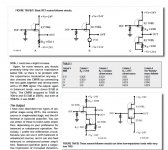
... My first thought was a simple SE CFP using a pair of BJT devices...
Using a JFET instead of a BJT at the input raises Zin and gets you rid of DC offset at the input and the output. BF862 is current production, high gm, low noise JFET. The buffer in attachment will effortlessly drive 2V RMS into 1k pot.
R2 will depend on your JFET's Idss and can be in range from 4R7 to 10R (right value will set your output DC offset at few mV and with P1 you can trim it down to zero).
CCS BJT will dissipate about 200mW so if you feel uncomfortable with it, use higher power device (BD139 or similar). Power consumption is about 20mA per rail, per channel.
Power rail voltage can be lowered by using a RC cells followed by 7x12 regs (or any other 10-12V regs of your choice).
Attachments
- Status
- This old topic is closed. If you want to reopen this topic, contact a moderator using the "Report Post" button.
- Home
- Source & Line
- Analog Line Level
- CFP Unity Gain Buffer