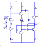
The J511 and equivalents have an impedance of around 120k with 25V across them.
When I measured the Early voltage of a BC860C (like Q1 in the OTA), I got 41 volts. The tables in 3rd edition of The Art Of Electronics say 30 volts (which is worse) for the BC860.
rout = (Vearly + Vce) / Ice
at 2mA, the collector impedance is 21.5K or 16K depending on which Early voltage you use. The 10 ohm emitter degeneration resistor R5 is less than Q1's internal emitter impedance (1/gm = about 13 ohms) so the degeneration increases Q1's output impedance by less than a factor of two. It is far less than 120K. So there is little benefit to increasing the impedance of the 2mA current source above 120K; it will have very little impact upon the Q1 stage gain.
And all of that assumes Q3's input impedance is infinity, which is not correct.
_
Attachments
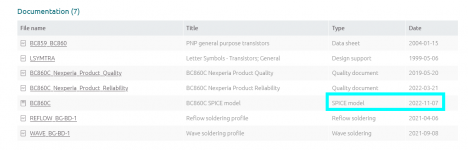
hoe is terrible for the BC860C, about a factor of four below "typical" small signal devices. Run it at Ic=2mA using the SPICE model on the manufacturer's website (link) and you'll see that Nexperia agrees with Horowitz and Hill's measurements, and also with my own: BC860C has got awfully low output impedance.
_
_
Attachments
Agreed entirely. I wouldn't use them for the output devices. Not sure what the hoe for the specified devices that the OTA-1 used. There were at least two and possibly three different devices used, presumably because they were obsoleted. The last ones were the 2N5321 and 2N5323, which are still available. I've searched the old databooks I have and googled - but I can't find what the hoe is.
OK - I found some characteristic curves in the 1975 RCA databook for the 2N5321 and 2N5323 http://ftpmirror.your.org/pub/misc/bitsavers/pdf/rca/_dataBooks/1975_RCA_Power_Transistors.pdf . That suggest that the Early voltage is about 1000V for these; the curves are so flat it is of course subject to some error. But since hoe ~ VA/Ic that comes out at about 1Mohm/mA. So for 5mA that would be hoe ~ 200k, so the NPN and PNP together would be about 100k.
Of course, in the end you take an OTA and load it with a resistor, so it ends up essentially being a voltage amplifier.
Of course who can say if current production devices have the same characteristics. I might buy a few and run them on the curve tracer and see.
Anyway, they look to be quite a lot better than the BC860C and complement with VA ~30V.
I was intrigued by the shiit loki mini circuit description, and when i have seen one b-stock on sale, could not resist.Yes, I'm aware of the Schiit unit. It has 7 opamps. Image from Schiit's own website. I think the lowest frequency band is a gyrator,
And it is a bargain, it has to be said.
View attachment 1116701
It does sound great. Off course 4bands are no substitute for 31bands of ultracurve i normally use.
Since most of my speakers are flat through midrange and highs, not much eq is needed there, mainly gentle tilt.
However, below 200Hz, room is requireing steeper eq than shiit offers.
So, i will still need behringer for 20 to 200Hz, and should be ok with 3 or 4 bands on top.
Hence i decided to build what ThorstenL presented, just with mid and highs eq. As soon as i get some coils.
Of note, about 30 years ago i attempted to build 15 band eq of socialist design, with coils, no feedback, but i had lots of hum and buzz and never finished the project. I see if i can look it up. Not sure if i kept the magazine.
I was intrigued by the shiit loki mini circuit description, and when i have seen one b-stock on sale, could not resist.
It does sound great. Off course 4bands are no substitute for 31bands of ultracurve i normally use.
Since most of my speakers are flat through midrange and highs, not much eq is needed there, mainly gentle tilt.
However, below 200Hz, room is requireing steeper eq than shiit offers.
So, i will still need behringer for 20 to 200Hz, and should be ok with 3 or 4 bands on top.
Hence i decided to build what ThorstenL presented, just with mid and highs eq. As soon as i get some coils.
Of note, about 30 years ago i attempted to build 15 band eq of socialist design, with coils, no feedback, but i had lots of hum and buzz and never finished the project. I see if i can look it up. Not sure if i kept the magazine.
Room EQ and "Remastering" Music require different EQ's.
For Room EQ I prefer parametrics but have also used the Behringer UC (8024 and 2496).
For Remastering something like the Palette is more intuitive.
I written a bit on the UC before. You may find this useful or not:
https://www.enjoythemusic.com/magazine/equipment/0101/behringer8024.htm
https://nielsio.blogspot.com/2007/11/thorsten-loesch-equalizers-speakers-and.html
I would also note that after correcting speakers for room issues I felt a greater need to correct individual recordings than without, I don't want to get into if that is a good or bad thing. Here is how I had things set up back then.
Thor
Thanks ThorstenL, I am familiar with your articles. I am familiar with 8024, have 3 in various systems, for more than a decade. Pretty much since it was available.
So i am used to work with it. Mostly using auto eq function with behringer mic. There are some advantages, and shortcommings. It clips much sooner than it indicates. It can easily have band overloaded and sound harsh, and so on. I have attenuator on input, and never use too much eq not to overload single band.
Its a powerful tool, but if i can replace it with better sounding analog eq, i would.
I think one thing I would add to any design is a peak clip indicator. That is often included with professional power amps like the good old C-Audio XLS602.
Unless you have a device with very high possible gain (e.g. mixing desk) I do not see a need, IF the design is made correctly with enough headroom.
In a power amp again it makes sense as there is a risk of overdriving the Amp.
With enough care adding them or not is not consequential so why not. But if everything is designed correctly, this blinkenlichten never lights.
Thor
Suppose the nominal signal level is 0dBu, and program peaks can be 20dB above that. Then you apply 20dB boost at a frequency extreme (such as 15Hz). So the nominal internal level is 40dBu and the unit is guaranteed to clip hard (unless the internal voltage rails were +/-100V or more)
A clip LED after each filter stage would be an easy thing to arrange and inform a reduction in input level.
Unless you do the whole thing in software, with automatic gain reduction. But that is not really the game we're playing in the long and winding thread.
A clip LED after each filter stage would be an easy thing to arrange and inform a reduction in input level.
Unless you do the whole thing in software, with automatic gain reduction. But that is not really the game we're playing in the long and winding thread.
Suppose the nominal signal level is 0dBu, and program peaks can be 20dB above that. Then you apply 20dB boost at a frequency extreme (such as 15Hz). So the nominal internal level is 40dBu and the unit is guaranteed to clip hard (unless the internal voltage rails were +/-100V or more)
A clip LED after each filter stage would be an easy thing to arrange and inform a reduction in input level.
Unless you do the whole thing in software, with automatic gain reduction. But that is not really the game we're playing in the long and winding thread.
For Hifi (and SE) we have 0.2V for your example above and 2V for a 20dB Headroom.
Applying 20dB boost at 20Hz would be highly unlikely for a recording that has a normal bass response.
I think clipping is unlikely even on 12V rails. Moreover, we are likely to overload the power amplifier much sooner. So put the peak LED's on the Amp.
Thor
Spent some time over the last few days looking at a Palette Pre "redesign" I did for a few "studio" friends. Added up to 6 DPDT band switches to allow "adjustment" of the center frequencies slightly: 20/40Hz; 80/120Hz; 400/800Hz; 1K/2Hhz; 5K/8Khz; 15K/20K/50khz. Switched caps ACROSS the pot and IN SERIES with the wiper. Adds versatility to the basic 6-band concept. Not too difficult to redo the switch frequencies BUT had trouble getting the "gain" to be the same between switch positions. That didn't really matter tho as when in use I'm setting things BY EAR. The home unit(s) I made up only switch the 400/800 and 1K/2K as these seem to be the "more useful" frequencies. If I were to do them over, would probably add 5K/8K. This design follows the P Pre with the 20/500/2K/20K sections in parallel followed by the 120/5K sections in series. The output resistors for the two series sections should be 10 ohms. Did find that the DC offset into the output amp was 30mv or so, so I put in a 5532 for the output amp with a DC offset adjustment.
Regarding a clipping indicator. For "home" use, the relatively small adjustments I may make to various frequencies don't affect the relative overall volume levels. So I never thought about nor envision a need for one.
Regarding a clipping indicator. For "home" use, the relatively small adjustments I may make to various frequencies don't affect the relative overall volume levels. So I never thought about nor envision a need for one.
Last edited:
The difficulty with both the National based Palette Pre, and the Audio Palette is that to keep gain and Q constant, changing frequency involves changing resistor values as well as capacitor values.
Douglas Self back in his 1976 Advanced Preamplifier Design, had comprehensive clipping indication. One for >1V peak and one for close to the +/-24V rails. He did not include that feature however in his later designs, which is perhaps telling.
Douglas Self back in his 1976 Advanced Preamplifier Design, had comprehensive clipping indication. One for >1V peak and one for close to the +/-24V rails. He did not include that feature however in his later designs, which is perhaps telling.
Douglas Self back in his 1976 Advanced Preamplifier Design, had comprehensive clipping indication. One for >1V peak and one for close to the +/-24V rails. He did not include that feature however in his later designs, which is perhaps telling.
I could see a point for a proper metering system with LUFS (or as we used to say VU - Volume Unit) and peak reading and the ability to meter the (gain adjustable) source (Pre-EQ), the level before the (naturally physiologically corrected) playback volume control (Post-EQ - this would be the normal use case setting) and on the output (calibrated against Speaker capabilities).
I don't see a simple clipping indicator in a preamp as useful.
Thor
A bit off track, but supporting the need for EQ, I went back to my system and did an EQ update (have been pending for too long as so much else ") )
)
Wrote a small post on the subject ... fb wellcome:
http://www.sensibleaudio.dk/2022/12/30/the-most-important-insight-to-good-sound/
Also I have spend too much time converting the OTA circuit to a workable (at least in TLSpice) opamp. Really like the tailless input with the fet and the bjt.
Gives quite low and predominantly 2. order distortion ...... think I'll do a pcb for it, even though I highly doubt it will sound different or better than modern opamps like OPA1642 ... but is a fun project
)Wrote a small post on the subject ... fb wellcome:
http://www.sensibleaudio.dk/2022/12/30/the-most-important-insight-to-good-sound/
Also I have spend too much time converting the OTA circuit to a workable (at least in TLSpice) opamp. Really like the tailless input with the fet and the bjt.
Gives quite low and predominantly 2. order distortion ...... think I'll do a pcb for it, even though I highly doubt it will sound different or better than modern opamps like OPA1642 ... but is a fun project
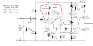
It's a Rush Cascode using a JFET and a BJT. Tubecad.com calls the configuration a "Bastode" and/or a "Retrogade Cascode".
I used Rush cascodes in a couple of Ship Of Theseus "Front End" boards: Kitty Hawk and Hornet. Full schematics, PCB Gerber files, and circuit descriptions are on the Forums, just use Search.
_
I used Rush cascodes in a couple of Ship Of Theseus "Front End" boards: Kitty Hawk and Hornet. Full schematics, PCB Gerber files, and circuit descriptions are on the Forums, just use Search.
_
Attachments
Cool ...... thought it was called tailless pair, after reading these:
https://www.4qdtec.com/pwramp.html
https://www.4qdtec.com/preamp.html
But much more hits on Rush Cascode
.... just realize it was used in NAD3020 phono input .... thought I had seen it before
...... thought it was called tailless pair, after reading these:https://www.4qdtec.com/pwramp.html
https://www.4qdtec.com/preamp.html
But much more hits on Rush Cascode
.... just realize it was used in NAD3020 phono input .... thought I had seen it before
Last edited:
Back to the Palette, I was looking at Burwen's original design for the Audio Palette. He was certainly not shy of using lots of opamps! Per channel there are:
24 unity gain buffers
6 servos to remove DC offsets
6 in the filter circuits
3 in the blender
2 in gain restoration following input and output gain controls
(that is not functionally complete)
The total count is 20 dual (NE5532AN) opamps per channel and 4 (dual) LF412ACN in the balanced input. He runs the 5532's at the maximum allowed voltage of +/-22V to preserve overload margin.
Not counting the power supply, muting after switch on, and switch/logic control of CMOS based signal switching for Bypass, LF Blend, and Phase invert.
The Cello Audio Palette implementation cut this down to 12 unity gain buffers (called voltage followers) and 12 opamps (6 OTA-1 and 6 OPA-2). So 24 discrete elements per channel as compared with 48 integrated circuit op amps. So roughly half the number of active elements and a shift from IC to discrete. It seems it also dispensed with all the signal switching gubbins and used real switches.
I'm not too sure of the final operating voltage of the Audio Palette, but I think it was +/-30V, so slightly greater overload margin as compared with Burwen's design.
- Home
- Source & Line
- Analog Line Level
- Cello Palette Style EQ Design (was High End Tone Control)...