Now you'll run into issues with the CCS compliance, but at least it will survive. I'd recommend (after replacing the CCS parts!) having about 20-25V on the grid (use a voltage divider with the upper arm bypassed) OR returning the CCS to a -20V supply if the grid is referenced to ground.
I think using CCS with -20V supply will omit one input capacitor at grid also.
I think using CCS with -20V supply will omit one input capacitor at grid also.
Would it? Wouldn't the grid voltage would be too high for the LM317 then?
EDIT: Maybe if a different, higher voltage CCS was used we could omit the capacitor if the gain stage (going to the grid) was run at a lower voltage?
EDIT: It just seems easier to use the cap and reference a low voltage to the grid, but I am open to ideas, as less caps is always a good thing.
Last edited:
Would it? Wouldn't the grid voltage would be too high for the LM317 then?
You can still use lower CCS negative rail in order to keep LM317 under the absolute max voltage limit by sufficient margin. Just amounts to common sense and a bit of tweaking
")
Isn't the grid is tied to GND itself by a grid bias resistor?
Last edited:
You can still use lower CCS negative rail in order to keep LM317 under the absolute max voltage limit by sufficient margin. Just amounts to common sense and a bit of tweaking
I'm still learning here, but that sounds to me like a negative voltage at the bottom of the LM317 would increase the voltage across the it, or am I misunderstanding this?
I'm still learning here, but that sounds to me like a negative voltage at the bottom of the LM317 would increase the voltage across the it, or am I misunderstanding this?
Try it with -10 to-15V, it will work for sure
Try it with -10 to-15V, it will work for sure
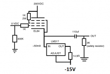
Yeah, I know I can do that so I don't have to reference a low voltage to the grid with the voltage divider, but I am fairly sure (thanks, SY!) that without the capacitor there the voltage at the grid will be very high (170 VDC) and cause the LM317 to fry because of the grid-to-cathode voltage.
Yeah, I know I can do that so I don't have to reference a low voltage to the grid with the voltage divider, but I am fairly sure (thanks, SY!) that without the capacitor there the voltage at the grid will be very high (170 VDC) and cause the LM317 to fry because of the grid-to-cathode voltage.
Voltage between your grid and GND will be almost zero if you use CCS return with -15V or so negative rail approach.
Voltage between your grid and GND will be almost zero if you use CCS return with -15V or so negative rail approach.
Can you show me a schematic? I think I must not be fully understanding
Can you show me a schematic? I think I must not be fully understanding
Chk
Attachments
The voltage on the grid wouldn't be 0 without the capacitor, it would be 170 (plus there wouldn't be a need for the 300K grid leak resistor). Would this still work in that case?
The voltage on the grid wouldn't be 0 without the capacitor, it would be 170 (plus there wouldn't be a need for the 300K grid leak resistor). Would this still work in that case?
Ok I give up
Ok I give up
On me, or the design?
I admit, new concepts aren't something I always grasp easily, and negative bias voltages are not something I am overly familiar with (but I understand them a bit).
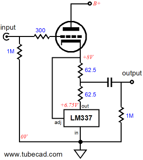
However, as SY told me already, the 170VDC grid to cathode voltage from the previous gain stage (a simple grounded cathode amplifier with the signal taken off the anode) is what was frying my LM317s and causing a low grid-to-plate voltage. The reason I put the cap there was to reduce the grid voltage to 0, then add the voltage divider to put 10 volts on the grid, in order to turn on the LM317.
Ok, I was not aware of the fact that the output of previous stage was coming from anode terminal, in that case the cap is needed for sure.
Only if the source or previous stage with zero offset is available, then you can omit cap while using CCS with negative rail approach.
Only if the source or previous stage with zero offset is available, then you can omit cap while using CCS with negative rail approach.
Ok, I was not aware of the fact that the output of previous stage was coming from anode terminal, in that case the cap is needed for sure.
Only if the source or previous stage with zero offset is available, then you can omit cap while using CCS with negative rail approach.
That's what I thought (and why I was confused at your suggestions). I probably should have drawn out a full schematic, but I was being lazy lol.
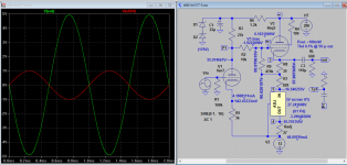
I come up with something like this. By adjusting R7 you can reduce power dissipation in LM317, provided it's above the current limit. R8 adjusts the V3 bias, the direct coupling is possible such that plate voltage is same as the dc voltage required to achieve V3 bias level. V1 supply is regulated to prevent non linearity due to voltage drop. V1 cathode is tied to -ve so the input level can be higher than if it is ground referenced, but output is limited to V3 bias level (can someone brighten me how to increase output?).
Attachments
There's really no need. There's more than enough power running it single ended
Whoever heard of enough power?There's really no need. There's more than enough power running it single ended
An externally hosted image should be here but it was not working when we last tested it.
- Status
- This old topic is closed. If you want to reopen this topic, contact a moderator using the "Report Post" button.
- Home
- Amplifiers
- Tubes / Valves
- CCS instead of a resistor in the cathode of a cathode follower?