Full ack to SY and DF96.
Concerning the 'belligerent' accusation: I wonder why people trying to give hard facts by making calculations are so often being harassed verbally in this forum, while on the other hand people claiming something 'feels as if it sounds better' are being congratulated to their success.
No one interested in hard facts?
Back to topic. Is my earlier question if real CCS or real voltage regs are closer to their 'ideal' counterparts answered by the calculations above?
Andreas
It might have been belligerent of me calling you belligerent, but at least I got to learn how to spell that word. Rude is probably better.
So are you saying an anode CCS is good to go or not? Seems to me you dont like that one either. If you do, then why is a CCS-bias so much worse?
Sure you can have your opinion, but last paragraph in post 13 isnt really that constructive either is it? I just felt like saying you could back off a little since you obviously dont know too much about this ckt.
Anyways, I agree the nonlinear parasitics in SS is probably worse than other non linearities we try to eliminate in audio designs. I cant really see it being a problem until one approaches low device voltage (low Vds or Vce). Tho I must admit I wonder how large voltage swings and high slew rates are affected by this capacitance. I like to think this is one of the paracitics giving some SS designs veiled sound...? Although a pentode isn't nearly as good a CCS as a SS version, it has none of the non-linear capacitances, and to me seems like a better anode load if a plain resistor is too boring. Havent tried that one yet either. Not sure I ever will, tho I just got curious...
Anyways 2, I wonder if OP will increase the negative voltage and try a CCS with full complience. I hope he does wether he or anyone else can explain why he feels it sound better than fixed bias. That's my opinion...
It is not easy to compare apples and pears, but we can try. The issue is the ratio of the source impedance to the relevant circuit impedance, combined with the expected nonlinearity. A CCS needs high and linear impedance; a voltage source needs low and linear impedance. The actual ratio can be scaled roughly according to the linearity: a 100 ratio with 1% distortion is about the same as a 1000 ratio with a 10% distortion.
For the parallel CCS the relevant circuit impedance is the source impedance from the preceding stage. I will guess a few k; people who are bothered can find a better figure. For a 1000 ratio we therefore need a CCS with impedance exceeding a few M over the audio spectrum. This is possible, but gets harder at the HF end. The CCS is facing a signal voltage of some 10's of volts, and approaching zero in one direction, so the AC is similar in magnitude to the DC - this create problems for this CCS which an anode CCS is less likely to face.
For the series voltage source the relevant circuit impedance is the 68k grid resistor. A 1000 ratio thus means that 68R is needed. However, if the voltage source has very low distortion (e.g. normal caps, resistors etc.) then more leeway is possible. The voltage source will have DC of 10's of volts and AC of 10's of mV so linearity is easy to provide.
The net result is that with a conventional voltage source the dominant distortion in the bias circuit is likely to come from the 68k resistor. For the CCS version the CCS itself is likely to be the dominant source of distortion in the bias circuit, although this is lkely to be severely swamped by the distortion from the previous anode. My conclusion is that this CCS bias is a poor solution for a non-problem.
Now if someone can estimate the likely distortion from signal current through a bias cap at a voltage source, and compare it with an estimate of the likely distortion of the CCS then I am happy to consider it. Otherwise I will stick with my diagnosis of faradophobia. (Incidentally, the coupling cap from the previous stage is likely to do far more damage to the signal - although still negligibly small).
See post 23 - the issue is the ratio between DC and AC across the CCS. This means that 'bias CCS' is likely to be much worse than anode CCS, unless a much better CCS is used. I suspect that CCS, especially in SS circuits, are not as ideal as some people imagine because all we ever see is impedance estimates or simulations (rarely measurements) and almost never anything on linearity.SemperFi said:So are you saying an anode CCS is good to go or not? Seems to me you dont like that one either. If you do, then why is a CCS-bias so much worse?
I was merely poking fun at people who are, apparently, sure of what they hear in spite of all the hard evidence which says that we can't be sure of what (we think) we hear. Perhaps I could have expressed the same thought more soberly and politely.Sure you can have your opinion, but last paragraph in post 13 isnt really that constructive either is it?
...if you (or anyone else) wants to show these advantages theoretically or experimentally, we're all ears, so to speak.
Theoretically: most of the modulated current doesn't go through the bias supply capacitor. Yes, I can hear how different capacitors sound when they are in the signal path...
Experimentally: it sounds a little better than my classic fixed bias. That is worth more to me than 10 pages of DF96's calculations.
The cascoded DN2540 is insanely better than you'd ever need (>100M impedance, noise in the pA range).
Unfortunately, the dynamic impedance is not constant, and is >100M only at low frequencies. But it doesn't go below 10M over the audio spectrum, anyway! That's a very good performance...
Unfortunately, the DN2540's impedance is pretty mediocre at low currents. For the 2mA you're seeking, a bipolar cascode will perform much better.
Yes, you are probably right. I used a 10M45s-DN2540 cascode CCS for this. I should try to measure the dynamic impedance at low (2mA) current, to see exactly how it performs.
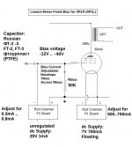
Anyway, I got the idea from here:
The diagram shows the idea. The Filament is heated normally, and a second regulator provides an adjustable current that is fed into the 50K bias resistor.
0.5mA gives 25V at very low noise - probably 100x lower than typical gas tubes. In fact the noise should be lower than with filament bias, since excess-noise in resistors in often proportional to current.
Recent regulators are temperature-compensated, allowing a stable supply to be developed. Why not give it a try!
Attachments
Rod Coleman (sort of) makes sense, in that excess noise in a resistor will be worse with more current. Hence the excess noise in the grid bias resistor will be smaller than excess noise in a cathode/filament resistor developing the same DC bias. However, noise is rarely an issue in output stages so it appears to be solving a non-problem.
The (minor) problem it does solve is that it avoids wasting power in a cathode/filament resistor, but if efficiency was an issue we would all be using Class D.
I note that Rod, unlike the OP, does not apparently make any comments about the dangers of signal current through bias caps.
The (minor) problem it does solve is that it avoids wasting power in a cathode/filament resistor, but if efficiency was an issue we would all be using Class D.
I note that Rod, unlike the OP, does not apparently make any comments about the dangers of signal current through bias caps.
I note that Rod, unlike the OP, does not apparently make any comments about the dangers of signal current through bias caps.
There's no danger; it's just my own preference, based on listening experience. I'm sure you can grasp the difference.
I agree that's purely subjective. So what? No mathematical model, no simulation can predict if an amplifier will sound "OK", "good" or "magical". The lowest possible THD never guaranteed enchanting musicality - we are using tubes after all, not solid state with tons of NFB.
So I have to rely mostly on my hearing. And this sense tells me to avoid capacitors in the signal path, if possible.
Good point.
With this R-C coupled schematic, the anode CCS of the first stage isolates its local PSU capacitor from the signal - that's not the case with transformer coupling.
Also, the CCS allows me to use a fixed (LED) bias for the first stage - that's another cathode bypass capacitor gone!
And the coupling cap is a good quality teflon, selected after extensive listening tests, which is smaller and better sounding than the big power supply capacitors needed for the transformer coupling.
So actually I have less capacitors in the signal path than I would if I used a cathode biased, transformer coupled stage.
Please don't get me wrong - I am not saying transformer coupling is bad. I am using it for my next project... BUT with some tricks to keep the caps out.
Hello,
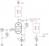
I can't figure this one out - what is causing this distortion and ruining a promising bias topology? (note: everything works perfectly with the classic fixed bias. The load is a 68K resistor as shown in the schematic.)
its not distortion. it is signal compression. I make a similar circuit for microphone preamps used in recording. your getting approx 2:1 compression ratio with auto makeup gain due to the css
Post 1 clearly shows distortion. Post 2 gives the most likely explanation, which was accepted by the OP.its not distortion. it is signal compression.
I hope music studios can tell the difference between distortion and compression.
Unfortunately, the DN2540's impedance is pretty mediocre at low currents. For the 2mA you're seeking, a bipolar cascode will perform much better.
Hello,
I have measured the dynamic impedance of the constant current sinks that I used, at low currents. The values are not very precise because I used an oscilloscope, but this should give us a general idea. I *did* compensate for the scope's input impedance, measured on spec at 1M.
Code:
[B]10M45S + DN2540 @ 1.5mA, 50v headroom:[/B]
 1KHz  -  300M (!?)
 2KHz  -  175M
 5KHz  -  69M
10KHz  -  36M
20KHz  -  23M
50KHz  -  17M

[B]MPSA42 + BC549 cascode, 2x green LED vref, @1.7mA:[/B]
 1KHz  -  15M
 2KHz  -  2M
 5KHz  -  315K
10KHz  -  100K
20KHz  -  36K
50KHz  -  11K (!??)
I am really surprised by the results: the MOSfet CCS measures way better than expected, the bipolar much worse???
- Status
- This old topic is closed. If you want to reopen this topic, contact a moderator using the "Report Post" button.
- Home
- Amplifiers
- Tubes / Valves
- CCS fixed bias