
I would hesitate to correct conventional wisdom on the basis of mere simulations, especially where the issue is distortion from a valve circuit. It is well known that valve models do not give reliable results for distortion.exeric said:I've been doing some further LTspice simulations using cathodynes (concertina, split load phase inverters). If I'm not wrong here, it seems myself and others may have been giving out erroneous info previously. It's a little hard for me to believe that such fundamental info could have been overlooked. I plead guilty also because I believed the conventional wisdom just like most people. This isn't a final verdict though because this just comes from LTspice simulations. It needs to be corroborated by others. I'll try to show what I'm getting at in a series of posts.
All about the cathodyne with (stop the presses) actual distortion measurements:
http://valvewizard.co.uk/cathodyne.pdf
http://valvewizard.co.uk/cathodyne.pdf
That's mostly true due to the poor quality of the tube SPICE models, nonetheless, the simulations are pretty good at showing the trend of distortion even if the absolute amount might be questionable. The takeaway from the above sim showed there is no reason why one can't make a decent direct-coupled cathodyne using the same B+ voltage as an AC-coupled one.I would hesitate to correct conventional wisdom on the basis of mere simulations, especially where the issue is distortion from a valve circuit. It is well known that valve models do not give reliable results for distortion.
What I'm getting at is that it's darn hard to direct couple a cathodyne from the previous stage and bias it at the optimum point.
That is why Zeus, in His infinite wisdom, invented step networks. It makes direct coupling and optimum biasing easy. See the ImPasse article for an example.
How about traying this one ? Just for the fun of itSo, the bottom line is it's a colossal waste of time to try to direct couple the concertina to the previous stage. It just is. You can get 105v PP out of a concertina supplied by just 300 volts if you do not direct couple. There is absolutely no need for a separate high voltage supply if you do that. If you are absolutely intent on removing a coupling capacitor then do it where it will do the most good: going into the finals using a power drive scheme, preferably a mosfet. Here's the output using that schemo and driving it with 120v P-P. It has an output of 105 v PP. There are tons of commonly available output tubes that require 300 v power supplies that can easily get by on that drive. And if you need more then at 450volts the concertina drive will scale up for the drive requirement for that.
One more thing. If you do not learn anything else then think of this. For most topologies you should use the concertina (not direct coupled from the previous stage) to drive the finals. The reason is that there will then be no deviation from phase symmetry by further amplification stages before the signal get to the finals.
")
Neon isn't needed for sim's.Is for preventing exessive Vgk at start-up.
Mona
Attachments
Not sure where the OP gets the "conventional knowledge" from, perhaps he can provide some links or references?
Maybe its not conventional wisdom. But as I learn, and I see others do it too, we all just took the earliest implementation of the cathodyne as gospel. In other words you almost feel like you have to fight your way out of the Williamson use of it. And then as you're doing that and have moved on you see repeated people coming after you and latching onto the same thing.
All about the cathodyne with (stop the presses) actual distortion measurements:
http://valvewizard.co.uk/cathodyne.pdf
Ok, presses are now shut down.
This is great reference material, Merlin. I'm going to be rereading this a lot.That is why Zeus, in His infinite wisdom, invented step networks. It makes direct coupling and optimum biasing easy. See the ImPasse article for an example.
Actually I have read it and have gotten some ideas from it.
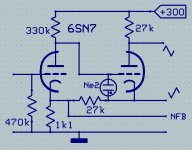
re: Ketje: "How about trying this one ? Just for the fun of it "
Positive Fdbk.
Normally one would be leery of injecting positive Fdbk into the main global N Fdbk node. It does still increase global N Fdbk loop gain, but also "corrupts" the N Fdbk node. Bad place to do that.
However, if the P Fdbk is particularly "clean" (suggest putting a CCS load on the 1st stage, and a very linear 1st tube), then it removes some of the unadulterated pure signal from the N Fdbk, increasing the proportion of actual error fed back. This then starts to look like an "Error Correction" scheme. Where the output error can be fully "nulled" with the appropriate amount of P Fdbk and N Fdbk. (the usual global N Fdbk schemes just get asymptotically closer to removing the error while approaching infinite loop gain)
Interesting. Who or what amplifier used this?
-
Last edited:
In SY's ImPasse preamp, there is a cathodyne phase splitter that couples its outputs to XLR jacks on the preamp, through XLR cables, to XLR inputs on a power amp.
In Merlin's Valve Wizard write-up, I saw this:
[book=Before finishing this section it is worth mentioning again that although the
cathodyne is an exemplary phase inverter, it is unsuitable as a balanced line driver.
When sending balanced signals down cables, the unbalanced source impedances
must be equal if we want good rejection of interfering signals (that is the point of
balanced signal transmission, after all). The cathodyne fails this criterion miserably;
it would allow far more interference to couple to the anode-driven output, which
would not be rejected by the CMRR of the receiving circuit at the far end of the
cable. In other words, the cathodyne needs to be buffered from the outside world.]%[/book]
If the cathodyne's two outputs are coupled to balanced inputs, is the above an issue?
In my particular situation, I have a 6GU7 cathodyne with outputs connected to 1/4" 3-conductor jacks, each with one meter of 3-conductor shielded mic cable going to 1/4" 3-conductor jacks on the inputs of my power amp. The cathodyne is running with a fairly high B+ and a healthy 8mA of plate current, with grid about -3V from cathode. If I remember correctly, plate-cathode voltage is about +110V.
The input circuit of the power amp is a differential-pair 6N6P, each with 220k grid-leak resistors. Is that an example of bad usage of a cathodyne phase splitter?
I'd think the above should be OK because each of the cathodyne's outputs see an identical load, namely the grids of each 6N6P triode section with 220k grid-leak resistors and an identical length of 3-conductor interconnect cable.
I figure the capacitance of each cable-plus-power amp input would be about 300pF. That's why I opted for higher current through the cathodyne, to avoid possible slew limiting.
Is the above a flawed approach?
--
Chris Paul correctly pointed out that the rejection on the plate side was inferior (and hence not equal to) the rejection on the cathode side. As a practical matter, I got no hum or noise pickup in my setup or the other ones I tried it in. But that's not to say this could always be counted on. If I were to redo the project, I would almost certainly add buffers.
It is done in the Harman Kardon HK20 amp.re: Ketje: "How about trying this one ? Just for the fun of it "
Positive Fdbk.
Interesting. Who or what amplifier used this?
-
Also the Philips HF309 and AG9015 .Sure there are more.
Mona
re: Ketje
Thanks! Very interesting to see this technique.
Hawksford EC does the positive Fdbk loop at the input to the final output stage (usually for SS). That works at larger signal level where linearity for P Fdbk is more difficult, but the SS outputs are typically followers, so little gain variation in the final loop.
This tube front end approach works with small signal level, where linearity is easy for the P Fdbk, but must contend with more gain variation in the global N Fdbk loop. (the P Fdbk must be clean and the global (open) loop gain constant for EC to accurately null the distortion) One could just tune out less than full error, allowing for the worst case tube aging in the global loop. But probably they have another "local" N Fdbk loop downstream to control the global (open) loop gain against aging or power supply variation, and so are able to tune out error to a "full null" with the P Fdbk loop. (well, best null, considering practical component accuracy and non-ideal 1st tube gain)
Will have to look up those amplifier schematics.
Last edited:
I've done it in a SS amp:
Part 1: https://linearaudio.nl/sites/linearaudio.net/files/UK-1 2008040241.pdf
Part 2: https://linearaudio.nl/sites/linearaudio.net/files/UK-2 2008050441.pdf
Writeup in general: https://linearaudio.nl/error-correction-power-amp
... but it aint tubes I'm afraid...
Jan
Part 1: https://linearaudio.nl/sites/linearaudio.net/files/UK-1 2008040241.pdf
Part 2: https://linearaudio.nl/sites/linearaudio.net/files/UK-2 2008050441.pdf
Writeup in general: https://linearaudio.nl/error-correction-power-amp
... but it aint tubes I'm afraid...
Jan
Chris Paul correctly pointed out that the rejection on the plate side was inferior (and hence not equal to) the rejection on the cathode side. As a practical matter, I got no hum or noise pickup in my setup or the other ones I tried it in. But that's not to say this could always be counted on. If I were to redo the project, I would almost certainly add buffers.
For the record, I've found no problem in my setup either.
If the cathodyne was converted to a 'source-o-dyne' (using a MOSFET instead of a tube), would that help matters? My thinking is that since the MOSFET will have higher gm and gain, it will be able to strong-arm its way to better noise rejection. Ya think it would be better, or not enough to make it worth the trouble?
--
Last edited:
On further thought, I don't think the positive feedback loop around the phase splitter (Ketje posted schematic) is actually constituting an EC (error correction) scheme, since the positive feedback signal also contains the N Fdbk signal. (so an ordinary gain boosting inner loop) It would take a separate (2nd) input tube to difference the N and P feedbacks and then sum with the input to do EC.
But the cathode of the input tube presumably has the negative output error term there, which would affect one of the splitter phases, since that is extended from that reference. One would have to simulate this, but it might be turning some residual distortion into even harmonics.
But the cathode of the input tube presumably has the negative output error term there, which would affect one of the splitter phases, since that is extended from that reference. One would have to simulate this, but it might be turning some residual distortion into even harmonics.
Last edited:
If the cathodyne was converted to a 'source-o-dyne' (using a MOSFET instead of a tube), would that help matters?
Probably not, unless you end up with much smaller drain and source resistors.
I guess this is getting a bit off topic for phase splitters. But one last observation. Global N fdbk usually goes back to before the phase splitter so the entire amp output is fixed up.
If one were to return the global N Fdbk to just one of the splitter phases, (and assuming class A output), then the remaining error in the amplifier would be all even harmonics. (and not fixable by the P-P OT, ie, signal corrupted) A resulting gain difference between the two phases would have to be dealt with of course.
Something of a long time quest for some maybe. Although I don't think it will produce the results expected. Low harmonics are more tolerable sounding, nothing to do with odd harmonics really, except 3rd is higher than 2nd. 1st harmonic is the best sounding.
The EC (or not) from positive Fdbk loop at the splitter scheme:
I'm not sure. Needs some analysis. It looks so close! But I think the P Fdbk is affecting the error component as well as the signal component at the input cathode. Needs to differentially affect the two.
Last edited:
- Status
- This old topic is closed. If you want to reopen this topic, contact a moderator using the "Report Post" button.
- Home
- Amplifiers
- Tubes / Valves
- Cathodyne investigation - stop the presses!