> what is in the PP OPT when one tube is in cutoff, or approaching?
When one side is nearing (it never gets there) cut-off, the other side is high current, high Gm. Using very rough rules of thumb, if the per-tube idle is 1/4 of the peak current, Gm tends to be similar for small or large signal. This optimum is not exact, very broad, and few designers even aim for it: most conditions work good, no condition eliminates distortion.
When one side is nearing (it never gets there) cut-off, the other side is high current, high Gm. Using very rough rules of thumb, if the per-tube idle is 1/4 of the peak current, Gm tends to be similar for small or large signal. This optimum is not exact, very broad, and few designers even aim for it: most conditions work good, no condition eliminates distortion.
Just to clarify:
A single-ended output stage can (and will) introduce both odd and even harmonics.
A push-pull stage (of any class: A, B, AB, or even C) with matched tubes, will not introduce any even harmonics but can (and will) introduce odd harmonics.
In normal circumstances, an output stage cannot eliminate distortion introduced in an earlier stage.
It is the variation in gain with signal which creates the distortion, so to say that the distortion is varying too is a misunderstanding. Sorry for not making that clear in my reply.20to20 said:OK, I understand the word no, in this case, means you disagree. Then, you say I might be double-counting the distortion... That's your counter enlightenment? No other explanation of what is in the PP OPT when one tube is in cutoff, or approaching?
A 2 stage SE amp:
With a driver tube at say 2% 2nd harmonic distortion, and an output tube at say 2% 2nd harmonic distortion, there will be a cancellation of the 2nd harmonic distortion.
This can work pretty well into a resistive load.
Problems with this method:
1. With changing signal levels, the driver and output tubes may not have the same 2nd HD, so the cancellation may vary at different power levels.
2. Loudspeakers are not resistive across the audio band, the impedance is complex (R, L, C; one, two, or all 3 at a particular frequency). The total complex impedance also varies with Frequency.
Therefore, the output tube 2nd harmonic distortion varies, and is no longer in step with the driver 2nd harmonic distortion, cancellation does not occur.
optimizing for the lower THD is not necessarily the best bias for class A to AB transition.
You have to listen different bias settings and also do the THD tests, often the best bias will result in similar THD numbers in Class A and class AB.
Unless you have the same:
/power transformer
/power supply
/output transformer
it is pointless to copy a certain amplifier bias point
You have to listen different bias settings and also do the THD tests, often the best bias will result in similar THD numbers in Class A and class AB.
Unless you have the same:
/power transformer
/power supply
/output transformer
it is pointless to copy a certain amplifier bias point
It's not the problem, that's the target! More precisely to make it more effective when level increases in order to have a "natural" curve of THD as function of Pout. If one doesn't get it then he has failed because he wasn't capable, with few excepetions that confirm the rule.Problems with this method:
1. With changing signal levels, the driver and output tubes may not have the same 2nd HD, so the cancellation may vary at different power levels.
Instead it is difficult to make it work over the full frequency range, even on dummy resistive loads. So, usually the range from 100Hz to 10KHz is given priority.
2. Loudspeakers are not resistive across the audio band, the impedance is complex (R, L, C; one, two, or all 3 at a particular frequency). The total complex impedance also varies with Frequency.
That is a problem for all types of amplifiers! If you have some 2nd harmonic cancellation it doesn't mean it will distort more.
It still occurs to a lower degree if done right.Therefore, the output tube 2nd harmonic distortion varies, and is no longer in step with the driver 2nd harmonic distortion, cancellation does not occur.
Last edited:
It's not the problem, that's the target! More precisely to make it more effective when level increases in order to have a "natural" curve of THD as function of Pout. If one doesn't get it then he has failed because he wasn't capable, with few excepetions that confirm the rule.
Instead it is difficult to make it work over the full frequency range, even on dummy resistive loads. So, usually the range from 100Hz to 10KHz is given priority.
That is a problem for all types of amplifiers! If you have some 2nd harmonic cancellation it doesn't mean it will distort more.
It still occurs to a lower degree if done right.
It is crazy, the only thing which works in the first stages is a cathode follower output with deliberately imbalanced resistors to counter the first stage triode second harmonics.
Also, try to bias the input grid to only -0.5V to -0.75V, you will be surprised, ps. needs regulation, the triode will have a lot less 2nd harmonics
This puts you in the region of grid current. Two options:gabdx said:Also, try to bias the input grid to only -0.5V to -0.75V, you will be surprised, ps. needs regulation, the triode will have a lot less 2nd harmonics
1. use a low source impedance so grid current does not create distortion
2. use a higher source impedance so grid current creates 2nd order distortion which partly cancels the distortion produced by the anode curves (so you get a lot less 2nd) but at the cost of much higher 4th, 6th etc. - in the early days of valves before they understood how horrible high order distortion sounds this technique was promoted.
you could feed the grid with a CCS at 40V and elevate the cathode with the same power source to 41V. This would be stable and benefit from a high linearity region and you cancel the 2nd harmonics in the driver stage (concertina stage or cathode follower) resistors mismatch. At certain voltages and current I could get the distortions down to minimum levels until valve or transformer clipping, with a minimal level of feedback.
Of course it wont give good results if you drive that grid with a 4 Vrms signal peak, but who does?
It gave me great results, didn't see horrible higher order distortion, a small increase in 3rd which is worth the trade off.
Of course it wont give good results if you drive that grid with a 4 Vrms signal peak, but who does?
It gave me great results, didn't see horrible higher order distortion, a small increase in 3rd which is worth the trade off.
Last edited:
How does elevating everything change anything?gabdx said:you could feed the grid with a CCS at 40V and elevate the cathode with the same power source to 41V.
Distortion cancellation only has merit when the two distortions arise from similar sources and so can be expected to vary with signal in a similar way. Balancing grid current distortion against anode distortion does not do this so is best avoided.
Some practical examples ( already posted in this forum)
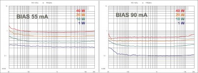
1- Fig. 6 is a double diagram abot the THD vs frequency with two bias current
At 90 mA the pp goes for more than 30 w in class A but also tha Rp of tubes goes down and it help. With 55 mA we have about 10 w in class A
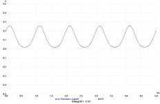
2- Fig 10
When the bias is set to 55 mA we have 10 w in class A ; this is a current monitor got at the cathode of one KT120. If you lokk on the bottom of the negative sino you can see a different shaper because it is approachin the AB class
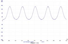
3- Fig 11
Same as above but we reach the 30 watt
If we go over this power the picture will one semi wave perfect and the other cut close to the line of 0, class AB
Walter
1- Fig. 6 is a double diagram abot the THD vs frequency with two bias current
At 90 mA the pp goes for more than 30 w in class A but also tha Rp of tubes goes down and it help. With 55 mA we have about 10 w in class A
2- Fig 10
When the bias is set to 55 mA we have 10 w in class A ; this is a current monitor got at the cathode of one KT120. If you lokk on the bottom of the negative sino you can see a different shaper because it is approachin the AB class
3- Fig 11
Same as above but we reach the 30 watt
If we go over this power the picture will one semi wave perfect and the other cut close to the line of 0, class AB
Walter
Attachments
How does elevating everything change anything?
Distortion cancellation only has merit when the two distortions arise from similar sources and so can be expected to vary with signal in a similar way. Balancing grid current distortion against anode distortion does not do this so is best avoided.
The point to is control this voltage and not let it depend on the cathode resistor but from a power supply which fixes the ratio grid/cathode.
With the mains voltage varies and amplifier power transformation saturating if it is a standard triode and the grid is only at -0.5 V the bias point wont stay there for long.
No, I still don't get it. If you want to set Vgk to -0.5V then the best way to do this is either use a diode or a resistor in the cathode i.e. normal cathode bias. As soon as you elevate both electrodes you are having to set the desired Vgk from the difference between two larger voltages, which is always a recipe for problems.
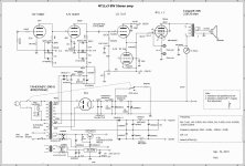
One excellent example of how harmonic cancellation should done can be found here in this forum and originally posted by user @michi. I re-attach the schematics with THD measurements in the bottom-side box here. Clearly there is no issue with grid current for the voltage amp stage. The ECC82 is just biased at low current with high anode load to provide useful cancellation with the cathode follower + output stage combo from 100Hz to 10KHz...and possibly even a bit more!
Attachments
Yes; there is no stage biased with Vgk of -0.5V.45 said:Clearly there is no issue with grid current for the voltage amp stage.
If, as you suggest, it is using two anode curves to balance off against each other then this is a legitimate use of distortion cancellation. Quite different from using grid current, as gabdx seems to be promoting.The ECC82 is just biased at low current with high anode load to provide useful cancellation with the cathode follower + output stage combo from 100Hz to 10KHz...and possibly even a bit more!
I am not promoting grid current, neither anode curves. There is little or no grid current in a small triode anyways..
Pardon my ignorance I don't see how the cancellation occurs in the schematic above.
Maybe there is a confusion because I am talking about PP and you are talking about the sun audio and another designer claim of using two triodes which would 'in theory' (lol) cancel each others harmonics'. Second harmonics are basically generated at triode and phase splitter and can be canceled.
It would be dreaming to say that a second triode cancels the harmonics of the first one. Moreover, because the signal is amplified you would need to create an imbalance in the first stage to match the higher 2nd in the last tube.
There is no way two triodes with different signal amplitudes and distortion characteristics can cancel anything.
Last edited:
One excellent example of how harmonic cancellation should done can be found here in this forum and originally posted by user @michi. I re-attach the schematics with THD measurements in the bottom-side box here. Clearly there is no issue with grid current for the voltage amp stage. The ECC82 is just biased at low current with high anode load to provide useful cancellation with the cathode follower + output stage combo from 100Hz to 10KHz...and possibly even a bit more!
Possibly one of the worst schematic I ever saw.
- Unstable direct coupling,
- resonant choke input power supply
- redundant useless power supply
- no feedback
- complicated for no reason transformers and chokes
- redundant stages
- improper drive and amplification
- basic and random values of components
- basic circuit worst than we did 60 years ago
- Very bad use of the pentode power, lacking output stage
I am not promoting grid current, neither anode curves. There is little or no grid current in a small triode anyways..
Pardon my ignorance I don't see how the cancellation occurs in the schematic above.
Maybe there is a confusion because I am talking about PP and you are talking about the sun audio and another designer claim of using two triodes which would 'in theory' (lol) cancel each others harmonics'. Second harmonics are basically generated at triode and phase splitter and can be canceled.
It would be dreaming to say that a second triode cancels the harmonics of the first one. Moreover, because the signal is amplified you would need to create an imbalance in the first stage to match the higher 2nd in the last tube.
There is no way two triodes with different signal amplitudes and distortion characteristics can cancel anything.
So now you say you are ignorant but then you would know how the posted amp works and pass nonsense judgments....
Last edited:
- Status
- This old topic is closed. If you want to reopen this topic, contact a moderator using the "Report Post" button.
- Home
- Amplifiers
- Tubes / Valves
- Cathode Bias confusion