Hi,
The board is looking good")
Do you use heatsinks? Otherwise the BD180 will overheat with 4 Ohm.
Clipping behaviour is bad, but in my opinion overcurrent protection
is more important. Do you have plans to add it?
And i noticed that the THD is far off your target, maybe this is due to the clipping diodes?
Greetings,
Udo
The board is looking good
Do you use heatsinks? Otherwise the BD180 will overheat with 4 Ohm.
Clipping behaviour is bad, but in my opinion overcurrent protection
is more important. Do you have plans to add it?
And i noticed that the THD is far off your target, maybe this is due to the clipping diodes?
Greetings,
Udo
Last edited:
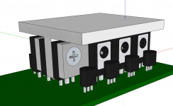
Please excuse the crudeness of the model shown. The idea for heat sinking is to bolt the inner two rows of transistors (these are the high-current ones) to a piece of aluminium T extrusion. I can use 2mm thick flat strip either side, one countersunk and the other threaded, to secure countersunk M3 screws.
Then the whole shebang gets slid down the middle. I can either thread the flat surface on top and bolt to a heatsink or just use the extrusion itself as the heatsink.
The flat strips either side make it so I can use double sided heat transfer tape to hold the driver transistor to the assembly, which will ensure they thermally track the output transistors. If this proves unnecessary I can forgo the flat plate bits and just use pan head screws and nuts.
The model shows a mockup of the output stage with one of the driver transistors removed for clarity.
Attachments
Not having read pages 4 - 13 of this very interesting thread, my questions may be outdated:
- What kind of load were these Spice simulations run with?
- Considering that it is usually the low load impedance the output stage is struggling with, why not consider connecting 2 - 4 drivers in series?
Higher voltage transistors are not that much more expensive, and they tend to be newer and more linear models. On the upside, 2 - 4x less components to solder, which is going to be a pain in itself even if cost targets are met.
Just wondering suzyj if you are aware that you can get high performance Sanken 2SC2837, 10A 100W
Ft=70 MHz devices for about $3 each?
2SC2837 Sanken | Discrete Semiconductor Products | DigiKey
There are also interesting Darlingtons that get you an extra transistor for free 2SD2390 $2.97,
perhaps a diamond in front of the Darlington if you must use one.
2SD2390 Sanken | Discrete Semiconductor Products | DigiKey
Last edited:
That raises an interesting point, Pete. While I'm comfortable building a diamond with a pair of say BD179 and BD180 transistors, plus a couple of smaller transistors for current sink/source, I'm less confident at using differing transistors for the drivers and followers, due to concerns about thermal runaway.
What's the go with thermal issues if the driver and follower transistors are different?
What's the go with thermal issues if the driver and follower transistors are different?
That raises an interesting point, Pete. While I'm comfortable building a diamond with a pair of say BD179 and BD180 transistors, plus a couple of smaller transistors for current sink/source, I'm less confident at using differing transistors for the drivers and followers, due to concerns about thermal runaway.
What's the go with thermal issues if the driver and follower transistors are different?
I've never designed or used a diamond before and I had to go back and look at your
design - okay I see now what you're saying and I'm not sure. I thought that the
parts I suggested might work in a diamond with cheaper drivers but I was offering
them even for use in a completely different design. I've never seen a full/detailed
analysis of a diamond buffer.
We had the $100 guitar amp challenge here, it might be interesting to have a $10
low-med power amp challenge say min 20W and use THD20 along with low PIM to
determine the winner.
Last edited:
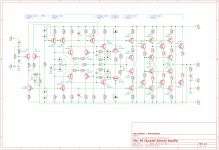
The linked simulation illustrates the point - using BD179/180 drivers and D44H11/D45H11 followers for the output stage, even with 1 ohm emitter resistors on the followers and no resistance on the drivers, I've got 33mA idle flowing in the follower stage with 11mA in the driver stage. My concern is that as the follower temp rises Vbe will drop causing us to lose control of output idle.
I guess I need to find a lower Vbe transistor than the BD179/180 with a more pronounced drop in Vbe with temp to use as a driver to ensure it all stays honest.
I guess I need to find a lower Vbe transistor than the BD179/180 with a more pronounced drop in Vbe with temp to use as a driver to ensure it all stays honest.
Attachments
The driver and follower should be on the same heatsink anyway. Otherwise the diamond
buffer current will run away.
The D44H11 has a greater max current (=larger die) than the BD180, and therefore a lower Vbe.
This is what i would want in a diamond, otherwise driver current is wasted.
This is a disadvantage of the diamond bufer. In a emitter follower, the driver
current is not wasted.
If you move the CCS diodes to the output thermal zone, it will give you a significant amount of NTC to bias current behaviour, then a minor tweak to Re of the drivers and their running currents will finalise the treatment.
But having different currents and resistor values in the diamond affects some other details that make the party trick work so careful consideration is needed.
But having different currents and resistor values in the diamond affects some other details that make the party trick work so careful consideration is needed.
Make the output stage out of D44H11 and D45H11 exclusively. Now you get back some of that sweet, sweet VBE tracking so fervently desired by Diamond OPS aficionados. ON Semiconductor offers it in the much smaller I-PAK thruhole package which may be just what you want in all positions except final final final output drivers.
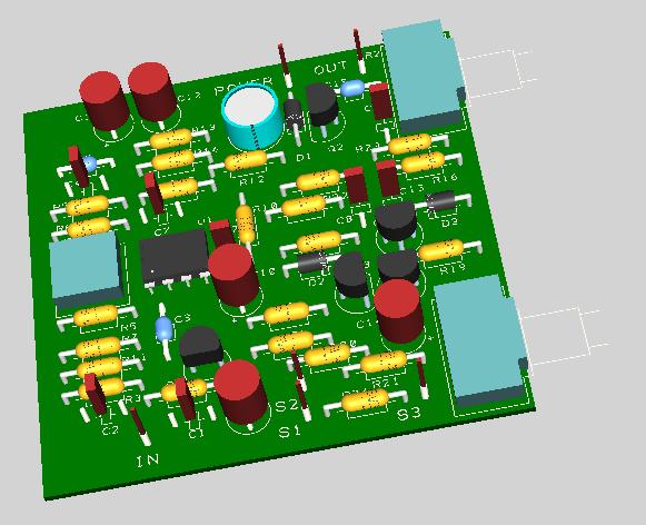
I've spent the last few days (holidays are fun!) using this design as an excuse to learn KiCAD.
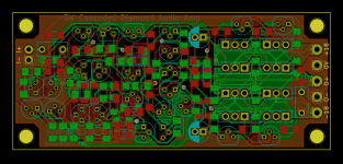
I must say I'm impressed. Coming from the various iterations of Protel and Altium, plus Cadence, KiCAD is refreshingly lacking in bloat. The schematics look really nice, and the editor is easy enough to drive. The PCB editor is a tad harder to come to grips with - I've not yet found a way to edit track widths except for defining widths in the design rules, and the library manager is quite a pain, wanting to use github versions of everything. The standard footprint for a TO-126 is broken, with pads on 0.1" rather than 0.09" spacing, and it took me ages to figure out how to duplicate the footprint to my own library and fix it. However it makes up for that with it's gorgeous pours that just work. And the 3D thing is a cute gimmick, even if the 3D models are pretty approximate.
But all of that fades into nothing compared to the simple fact that it's free open source software, unlike any other PCB CAD tool I've ever used.
Attachments
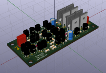
That looks tiny! Something to try for sure.
Thanks Chris. I'm pretty happy with the layout - by using both sides with 1206 caps and MELF resistors I've kept things pretty compact, which in turn should keep parasitics down.
Make the output stage out of D44H11 and D45H11 exclusively. Now you get back some of that sweet, sweet VBE tracking so fervently desired by Diamond OPS aficionados. ON Semiconductor offers it in the much smaller I-PAK thruhole package which may be just what you want in all positions except final final final output drivers.
That is so very cool. And all of 44c ea in 100 off quantity, too. The PCB I posted yesterday will work with these little guys, which will be useful for prototyping...
D44H11/D45H11 have quite bad SOA, for a 5W amp - maybe okay but I don't even
like them as drivers for a higher power amp:
https://www.onsemi.com/pub/Collateral/D44H-D.PDF
.6A at 30V = 18W for Onsemi, STmicro claims much better 1A at 30V:
http://www.st.com/content/ccc/resou...df/jcr:content/translations/en.CD00000942.pdf
like them as drivers for a higher power amp:
https://www.onsemi.com/pub/Collateral/D44H-D.PDF
.6A at 30V = 18W for Onsemi, STmicro claims much better 1A at 30V:
http://www.st.com/content/ccc/resou...df/jcr:content/translations/en.CD00000942.pdf
Last edited:
Did you happen to notice Design Spark, it is also free. I was up and running after
doing the tutorial:
Our Software
But I never went so far as to have boards made.
Ross Compressor Guitar Pedal Clone:
doing the tutorial:
Our Software
But I never went so far as to have boards made.
Ross Compressor Guitar Pedal Clone:
Last edited:
I use designspark as my free editor but the stock libraries I found to be more or less broken. Modelsource was sometimes handy but the symbols for anything that you didn't want to make a model for are typically generic bricks with no useful labelling, and also the consistency was sub par - diodes, resistors etc with inconsistent styles and sizes made a mess of the schematic. I generate my own models both so that they are consistent and as well so I don't need to blame anyone when it turns out the promised model for a part is actually broken. The wizard works alright to get a model started once you get your head around it.
- Home
- Amplifiers
- Solid State
- Cascading diamond buffers - a cheap low THD 10W amp with TIP41C