Which is what I said. However given a 3k6 undistorted signal component at say 1V and a second harmonic of 1k8 at 1V, what is the difference? None.The idea is that you can cross a driver over electrically so that the fundamental frequency doesn't excite the resonance, but in operation, you can play frequencies that are in the operational range of the driver, but their distortion harmonics ring in the driver acoustically, regardless of the crossover frequency.
Let's say a driver has a cone breakup resonance at 3.6 khz. If you cross this driver over at 2khz and then play a 1.8 khz tone, the first harmonic is going to be at 3.6 khz, which will ring the cone at it's breakup frequency, unless I've made a grave error in my research of resonances.
Electrical Harmonics Calculator
Now how bad is the distortion going to have to be to get it at a significant level where this is a major problem? Even if the 2H is at 10% it is still 20dB below fundamental and for the 2H to be at this level, the 1H is going to be 10V.
Now how bad is the distortion going to have to be to get it at a significant level where this is a major problem?
Well, we know how far down we need resonance to be (in -db) so we should be able to extrapolate, given distortion levels how far down we need the harmonics to be.
Just for the sake of argument, if we assume -50db is acceptable for a cone resonance, what is the level of the first harmonic distortion frequency if the primary frequency falls within the range that the driver is playing? If we play a fundamental who's first distortion harmonic excites the resonance and that first harmonic happens to coincide with a breakup frequency, is that 2nd harmonic still -50 db? It depends on the amount of distortion, and I think if measured, you'd find that the distortion of most drivers is a large enough percentage that the multiples excite the resonance of the driver quite a bit more than -50db.
Edit: We have to remember that resonances are produced by the driver and aren't filtered by the crossover.
Brett,
Of course you are right that 4 kHz is 2.3 octaves above 800 Hz. What an embarrassing mistake- it always helps to put your brain in gear before making a reply.
Regards,
Pete
Of course you are right that 4 kHz is 2.3 octaves above 800 Hz. What an embarrassing mistake- it always helps to put your brain in gear before making a reply.
Regards,
Pete
Hi,
Your not looking at the problem in the correct manner IMO.
Peaks in a drivers bandwith / roll-off give it an elliptical response,
and the fairly obvious corollary is a converse elliptical filter function.
Elliptical allows a notch filter in the low pass roll-off.
This will and does work a lot simpler than cascaded low pass filters.
A great example : Zaph|Audio

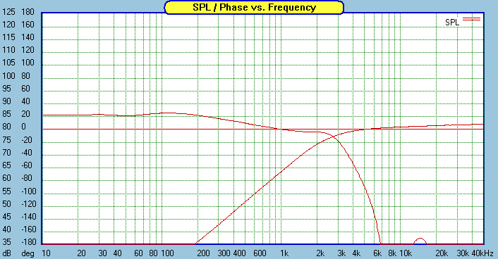
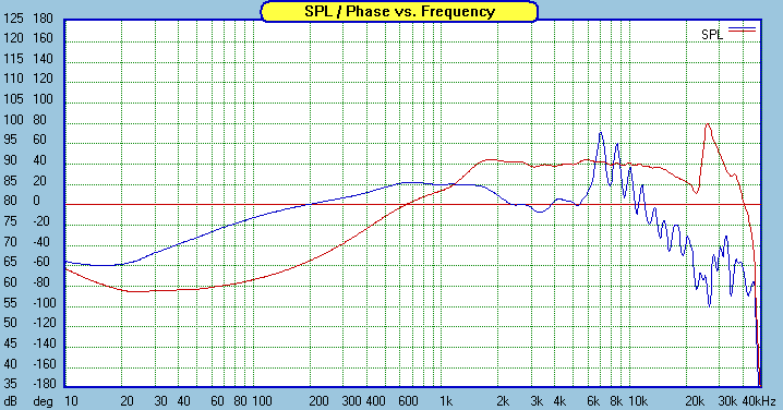
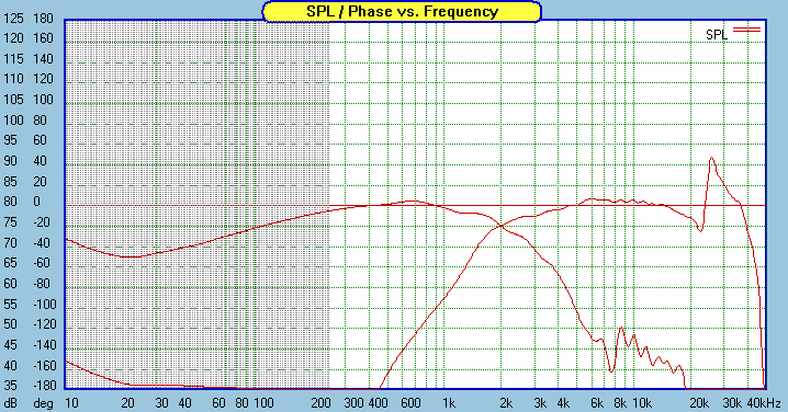
Note the electrical low pass is not monotonic, it peaks back up above the notched frequency.
rgds, sreten.
Your not looking at the problem in the correct manner IMO.
Peaks in a drivers bandwith / roll-off give it an elliptical response,
and the fairly obvious corollary is a converse elliptical filter function.
Elliptical allows a notch filter in the low pass roll-off.
This will and does work a lot simpler than cascaded low pass filters.
A great example : Zaph|Audio

Note the electrical low pass is not monotonic, it peaks back up above the notched frequency.
rgds, sreten.
Last edited:
Just so we have some perspective on the nature of these break up regions with hard cone woofers, here are a couple links to the spec sheets on some Dayton Reference drivers
Dayton Reference RS-180-8 -
http://www.parts-express.com/pdf/295-355s.pdf
Dayton Reference RX225-4 -
http://www.parts-express.com/pdf/295-376s.pdf
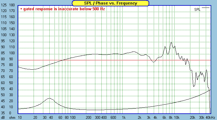
Notice that the break up region is substantially louder than the working range, in the case of the RS-180 the break up can be 25db to 30db louder than the working range.
And while the break up starts around 4K, it easily spans a range of 4k to +10k with the peak at approximately 6khz to 8khz.
That seems a pretty wide band to try and suppress. And also a pretty high amplitude to try and suppress.
There are a lot of speaker systems that use the Dayton Audio reference, so people must have found a way to deal with it.
Just a thought.
Steve/bluewizard
Last edited:
Hi,
Example of of an elliptical low pass for the RS180 : Dayton RS180 2-Way
I prefer Zaphs graphs, RS180 :

rgds, sreten.
Example of of an elliptical low pass for the RS180 : Dayton RS180 2-Way
I prefer Zaphs graphs, RS180 :

rgds, sreten.
Last edited:
probably it would be okay to first get a proper circuit simulator.
then,
http://www.wavecor.com/Transducer_equivalent_circuit.pdf
check if you can make this for the speaker, and simulate it in the software.
you would need impedance correction in order to crate a filter that manages to roll off the nasty peak, then design your intended crossover keeping in mind the final impedance seen by the crossover network.
probably it would end up as:
2nd order lowpass, zobel, nother low pass (1st or 2nd order), nother zobel.
Then you would have to check out the phase response, and other functions of the whole unit.
huge challange.
I don't claim to know much about crossover networks and interaction between cascaded networks, but placing a notch filter at the offending breakup frequency amounts to a similar thing, both a HP and LP filter together, instead of just an additional cascaded LP filter suggested by the OP.
Just that no one thinks twice about interaction with a notch filter, or even a BSC circuit with the main XO circuit.
Just that no one thinks twice about interaction with a notch filter, or even a BSC circuit with the main XO circuit.
Member
Joined 2009
Sreten pointed out an implementation that Zaph did for a very similar driver. I find it somewhat unusual but very enlightening.
Seas L18 / Seas 27TBFCG
I don't think it will hurt to repeat the simple rule for crossovers, which has no doubt been expressed throughout this thread many times already.
"In general, the electric slopes don't matter as long as they take us to the correct acoustic slopes."


Seas L18 / Seas 27TBFCG
I don't think it will hurt to repeat the simple rule for crossovers, which has no doubt been expressed throughout this thread many times already.
"In general, the electric slopes don't matter as long as they take us to the correct acoustic slopes."


Dayton RS180 2-Way
Hi, If didn't make it clear, Zaphs approach used with the RS180, rgds, sreten.
(I first saw it on Zaph's site, but he makes no claim regarding originality.)
Hi, If didn't make it clear, Zaphs approach used with the RS180, rgds, sreten.
(I first saw it on Zaph's site, but he makes no claim regarding originality.)
- Status
- Not open for further replies.
- Home
- Loudspeakers
- Multi-Way
- Cascading Crossovers - Just a Thought.