Hi there, new to DIYaudio, and I"ll get to posting soon (I usually hang out at CarverAudio).
I've been experimenting with Carver M-500, M-500t and M-1.0t amplifiers, and have developed a stable, reliable upgrade I call the mk II series.
see carvermk2.com for more information, and email me if you need more info.
Thanks,
Rich
I've been experimenting with Carver M-500, M-500t and M-1.0t amplifiers, and have developed a stable, reliable upgrade I call the mk II series.
see carvermk2.com for more information, and email me if you need more info.
Thanks,
Rich
Hi Rich,
Good to see you. I was factory warranty for Carver in Canada for a while, until AC Simmons went down. I had sold my company by that time.
I've heard bits about your upgrades, and have some concerns relating to running the supply voltages higher - that's one thing I've heard anyway.
I find these amps are very reliable if they are serviced occasionally. Those lower tier filter caps have a rough life with the waveform they have to deal with. The larger 130V caps are one thing I have only rarely had to replace. Normally after a "tech" shorts out the triac in an attempt to defeat the protection.
So, were you in the service department, or engineering?
-Chris
I wasn'y an engineer yet back then (I was still a kid) and it was a part time gig. I was in the USAF, and my boss, who worked at Carver, brought an M-500t in over Christmas break. He said anybody who could fix it could have the repair money. The service manual was only a schematic, but for some reason it made sense to me. He PCS'd a couple of months later and I got his job at Carver (inherited a couple of his 'boat anchors' too ;(
Hi Rich,
The M-500t was possibly one of the prettier Carver amps. It looks fantastic in champagne gold. Those are the European models called "Bennytone".
Most of the early Carver service information was simply a schematic. A few later ones detailed how his circuits worked. I lost all my manuals, Carver included, when I sold my shop. I do have the modifications still, and a couple later products. The Lightstar product was a return to the drafting size paper with schematics only. I still have one output PCB with a hole where the feedback resistor used to be.
The Carver "Cubes", M-400 X, were more difficult to work on. I think that manual had a circuit explanation in it. Once you get used to working on them, it's only time and patience.
What did he leave you when you got his job?
-Chris
anatech said:.....Most of the early Carver service information was simply a schematic. A few later ones detailed how his circuits worked. I lost all my manuals, Carver included, when I sold my shop.
Yes, the later manuals were much more descriptive re theory of operation.
......The Lightstar product was a return to the drafting size paper with schematics only. I still have one output PCB with a hole where the feedback resistor used to be.
The lack of available schematics for Sunfire is what got me into this in the first place. When I got into re-building my setup, I ended up with 4 M-500t mk II, 3 M-1.0t mk II and 1 M-1.0t mk II opt 002.
I want to be able to work on my own equip, instead of paying $600 flat fees. Otherwise, I could have gotten away with a couple of Sunfire multi-channel amps
")
......What did he leave you when you got his job?
-Chris
IIRC he had toasted a couple of M-1.0t's by shorting across the triac in an attempt to 'jump start' the power supply.
I guess I was at an advantage because, being a newbie to electronics, I wasn't 'ingrained' with common troubleshooting techniques and circuit behavior.
I really admire the triac controlled field coil design, and tiered rails, very clever
Hi Rich,
-Chris
Edit:
Oh god!!! Not wise at all!IIRC he had toasted a couple of M-1.0t's by shorting across the triac in an attempt to 'jump start' the power supply.
-Chris
Edit:
That was never proper procedure - ever! I use a variac with a shorted triac. You're safe up to about 40 VAC. You can troubleshoot faults with reduced voltages. I've found faults as low as 10 VAC input. Besides, the amp tries to come on. It cycles on and off by itself. These amps do everything to prevent further damage and even try to help you figure out the fault.I guess I was at an advantage because, being a newbie to electronics, I wasn't 'ingrained' with common troubleshooting techniques and circuit behavior.
That took Bob a lot of work to get right. The protection circuits are also part of the triac control as they shut the amp down. Anyway, getting the firing angles matched between cycles to prevent uneven firing was an issue in the M-400 products, and some newer too.I really admire the triac controlled field coil design, and tiered rails, very clever
anatech said:......That was never proper procedure - ever! I use a variac with a shorted triac. You're safe up to about 40 VAC. You can troubleshoot faults with reduced voltages. I've found faults as low as 10 VAC input. Besides, the amp tries to come on. It cycles on and off by itself. These amps do everything to prevent further damage and even try to help you figure out the fault.
Yes, a variac is the way to go, but as improper as it is, MANY techs have tried the triac jumper 'trick' only to end up with a pretty box of iron.
.....That took Bob a lot of work to get right. The protection circuits are also part of the triac control as they shut the amp down. Anyway, getting the firing angles matched between cycles to prevent uneven firing was an issue in the M-400 products, and some newer too.
I saw that in some of the ECO's and TCO's re uneven firing angles.
Hi Rich,
I got most of the attempts to repair on my bench, some were pretty bad. That is why I'm so sensitive about untrained people getting into these amps. The rules have changed, as Bob Carver designed them.
Ever see a PM-1.5 that was plugged into 550 VAC? The arc from inside one of the power transistors cut through the top of the can. It also cut through the bottom cover plate over the outputs. I've seen a few where the arc cut the top of the can, but only one where the amplifier cover was cut also. Didn't fix that one. It needed ..... everything. Even the circuit boards were done. Case was marked up, so that amp was a complete loss. Poor thing.
I think the protection/power supply circuits were one of the best. Smart shut down and reduced weight and heat as side benefits. It's just that they needed to use switching supply capacitors that could take those current spikes better.
Which brings me to another question for you. The use of small capacitors was done for a reason. You have increased the capacitance. Was that an availability thing, or towards something more material? This power supply was designed to work with lower capacitance than normally used as it had the ability to draw huge amounts of power from the AC supply when required. You did not have the normal tiny charge period that a normal supply has to deal with.
If your design is something you don't want to detail, then that's okay. You can always PM me as well.
-Chris
We went through hell with that in Canada. Because these mag coils draw so much current when fed 120VAC, we also sold many mag coils. That's even after advising the "tech" that this behavior was normal and that there would be no refund. Just plain hell. Then there were the "warranty shops" that had to be shut down due to destruction. Most were dealer service, but the entire province of Quebec ended up with no warranty shops. Must have been a cultural thing, 'cause they just would not listen.Yes, a variac is the way to go, but as improper as it is, MANY techs have tried the triac jumper 'trick' only to end up with a pretty box of iron.
I got most of the attempts to repair on my bench, some were pretty bad. That is why I'm so sensitive about untrained people getting into these amps. The rules have changed, as Bob Carver designed them.
Ever see a PM-1.5 that was plugged into 550 VAC? The arc from inside one of the power transistors cut through the top of the can. It also cut through the bottom cover plate over the outputs. I've seen a few where the arc cut the top of the can, but only one where the amplifier cover was cut also. Didn't fix that one. It needed ..... everything. Even the circuit boards were done. Case was marked up, so that amp was a complete loss. Poor thing.
Most were not that bad. Aside from some triac failures (blown fuses and popped capacitors), most just had uneven firing. Tickity - tick - tick - tickity .... on and on. They evened out under load. Once they went to transistor firing circuits and away from diacs, things were much, much better. Still, Bob had to go to great lengths to get that sorted out.I saw that in some of the ECO's and TCO's re uneven firing angles.
I think the protection/power supply circuits were one of the best. Smart shut down and reduced weight and heat as side benefits. It's just that they needed to use switching supply capacitors that could take those current spikes better.
Which brings me to another question for you. The use of small capacitors was done for a reason. You have increased the capacitance. Was that an availability thing, or towards something more material? This power supply was designed to work with lower capacitance than normally used as it had the ability to draw huge amounts of power from the AC supply when required. You did not have the normal tiny charge period that a normal supply has to deal with.
If your design is something you don't want to detail, then that's okay. You can always PM me as well.
-Chris
I'm not keeping it to myself; the parts list is posted at Carveraudio.com, and I'll help anybody who wants to do it to their own amp........Which brings me to another question for you. The use of small capacitors was done for a reason. You have increased the capacitance. Was that an availability thing, or towards something more material? This power supply was designed to work with lower capacitance than normally used as it had the ability to draw huge amounts of power from the AC supply when required. You did not have the normal tiny charge period that a normal supply has to deal with.
If your design is something you don't want to detail, then that's okay. You can always PM me as well.
-Chris [/B]
The capacitance thing......I did this in two stages.
After researching datasheets (and these forums as a lurker) I came up with a preliminary parts list. Once everything was installed, I initially bumped the rail + 10 VDC, and got the following:
(m-500t)
Original:
RMS <0.15 THD
8-----283W
4-----332W
Dynamic
8-----387W
4-----474W
2-----412W
Mk II Stage I
RMS <0.15 THD
8-----373W
4-----410W
Dynamic
8-----410W
4-----702W
2-----947W
This showed a substancial increase, especially in dynamic power, where the original tended to sag. Next, it tickled the rail another +10VDC (the two tiers were 35 and 74, now they're 45 and 95), and put the highest capacitance I could fit into the dimensions available. I got the following:
Original:
RMS <0.15 THD
8-----283W
4-----332W
Dynamic
8-----387W
4-----474W
2-----412W
Mk II Stage I
RMS <0.15 THD
8-----373W
4-----410W
Dynamic
8-----410W
4-----702W
2-----947W
Mk II stage II
RMS <0.15 THD
8-----380W
4-----420W
Dynamic
8-----519W
4-----926W
2-----1145W
Bridged
8-----820W
Not much of an increase with a steady sine signal, but dynamic power was substantially raised again.
The higher capacitance was more of an empirical experiment than a calculated plan; Overall, increasing the capacitance yielded a 40W (with RMS signal) or so gain, so I kept them in.
I then took a non-contact thermometer to the heatsink center and found:
into 8R at full bore for 20 mins:-----120 F-----mag coil @ 125 F
into 4R at full bore for 20 mins:-----140 F-----mag coil @ 135 F
Stock unit
into 8R at full bore for 20 mins:-----115 F-----mag coil @ 120 F
into 4R at full bore for 20 mins:-----135 F-----mag coil @ 130 F
So at most a 5 or 10 degree F difference in heat dissipation; probably attributable to the increased voltage drop across the outputs with the same amount of heatsink.
While I'm doing a burn-in (I do 96 hrs into 1/4 power at 4R) I occassionally walk over and give her full boost. Into static 4R dummy loads (not reactive loads like speakers, but quieter
I haven't been able to shut one down through thermal protect.One owner is driving 4R Magnepans, and reports no issues with heat.
One Carveraudio member who demo'd a unit on his Carver ALS's was able to shut her down under thermal protect......they definitely won't drive Carver amazings. He was also comparing to his Sunfire (load invariant design).
Hi Rich,
Yes, the increase in heat is due to higher voltages.
Shutdown. You have not modified the over current protection, so the original shutdown levels are at the original settings. A good thing in my book.
ALS speakers were always hard to drive, along with many other silly designs. I wouldn't worry about that. I had a Lightstar amp, that would toast those speakers. No point though. I had to sell that one as I couldn't justify keeping it. One of Carver's nicer sounding amplifiers.
My feeling is pretty simple on speakers. If they are hard to drive, they will never sound as good as they would have if they were designed properly. That hamstrings the speaker unnecessarily. Why do that?
You should measure the pre-driver case temperatures. The drivers and outputs are on heat sinks, the others are more critical possibly. You should (if you have the time) try your normal mod, but with the lower capacitance values. I don't think they will materially affect the sound with live music. Also, since the supply is regulated, the RMS values are a truer test I think. Here the Carver design should shine compared to a normal design. Of course, for a Caver winding out, you need a stiff AC supply. That may affect your readings more than the internal capacitance. Just a thought.
I am curious what test gear you are using. Professional curiosity since you are doing so much higher energy work. Keep in mind that most Japanese THD analyzers have internal HF loss between 30 and 40 KHz. Something that will go up beyond 500 KHz might be better. This is especially true for looking at commutation noise. I look at the residuals out of a THD analyzer triggered from the speaker out on a dual trace scope. You can see these glitches very clearly then. A purpose built spectrum analyzer is even better some times.
-Chris
.....My feeling is pretty simple on speakers. If they are hard to drive, they will never sound as good as they would have if they were designed properly. That hamstrings the speaker unnecessarily. Why do that?
I feel the same way; I'm running two pair of Cornwall II, in a 'poor man's Duntech Sovereign' D'apolllito config; very efficient and quite dynamic.
....I am curious what test gear you are using. Professional curiosity since you are doing so much higher energy work.
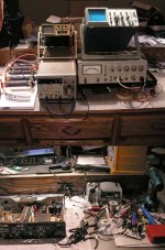
Here's a pic of my gear, nothing fancy, I'd LOVE to have a specan or one of those newer LCD O'scopes that do some freq domain things, but I'm not a business, just an enthusiast with a soldering iron
.... I look at the residuals out of a THD analyzer triggered from the speaker out on a dual trace scope. You can see these glitches very clearly then. A purpose built spectrum analyzer is even better some times.
Thanks for the tip; I'll certainly give it a shot.
-Chris [/B][/QUOTE]
Attachments
Hi Rich,
We use the same THD analyzer. This model is the very best one I have used to date. It does take some getting use to though.
I recently demo'd five digital models. The Aglilent 5000 and 6000 series, Tek DPO 4000, LeCroy (forgot the model) and a Rigol 100 MHz (I think). From the perspective of someone who uses analog scopes, the favorites stacked up like this: Agilent 6000, LeCroy, Agilent 5000 and Tektronix. The Rigol was dead last but not terrible. Why did I not like the Tek that much? Simple, it doesn't fit where a normal 'scope fits (same as the Agilent 7000 series - I also don't like), it runs very hot and tends to be noisy and it ain't intuitive at all compared to Agilent and LeCroy.
All these 'scopes have some connection to network or USB (or both) and you can capture the data onto a computer. All were very easy to set up on a network (where applicable). Tek was as good as Agilent and LeCroy in that regard.
For noise, starting form quiet to loud: Rigol, Agilent 6000, LeCroy, Agilent 5000 and Tektronix. The Agilent seems to run the coolest of the larger 'scopes.
I would like to save up for the Agilent 6000 series, the prices will probably come down some as the cost DSP processing comes down. It is packed with excellent features and can be converted to an MSO 'scope (16 data channels) with decoding.
I'm also a home experimenter really. I was able to pick up an Agilent 3585A swept signal spectrum analyzer. I have found it to be incredibly useful. They normally run $1,500 USD and up.
Looking at your residuals can give you all kinds of data. Hanging a spectrum analyzer off that should extend the S/N range too.
-Chris
We use the same THD analyzer. This model is the very best one I have used to date. It does take some getting use to though.
Forget the digital 'scopes for now. The resolution isn't that great, nor is the dynamic range. They are good for rough things (like checking for oscillation).I'd LOVE to have a specan or one of those newer LCD O'scopes that do some freq domain things
I recently demo'd five digital models. The Aglilent 5000 and 6000 series, Tek DPO 4000, LeCroy (forgot the model) and a Rigol 100 MHz (I think). From the perspective of someone who uses analog scopes, the favorites stacked up like this: Agilent 6000, LeCroy, Agilent 5000 and Tektronix. The Rigol was dead last but not terrible. Why did I not like the Tek that much? Simple, it doesn't fit where a normal 'scope fits (same as the Agilent 7000 series - I also don't like), it runs very hot and tends to be noisy and it ain't intuitive at all compared to Agilent and LeCroy.
All these 'scopes have some connection to network or USB (or both) and you can capture the data onto a computer. All were very easy to set up on a network (where applicable). Tek was as good as Agilent and LeCroy in that regard.
For noise, starting form quiet to loud: Rigol, Agilent 6000, LeCroy, Agilent 5000 and Tektronix. The Agilent seems to run the coolest of the larger 'scopes.
I would like to save up for the Agilent 6000 series, the prices will probably come down some as the cost DSP processing comes down. It is packed with excellent features and can be converted to an MSO 'scope (16 data channels) with decoding.
I'm also a home experimenter really. I was able to pick up an Agilent 3585A swept signal spectrum analyzer. I have found it to be incredibly useful. They normally run $1,500 USD and up.
Looking at your residuals can give you all kinds of data. Hanging a spectrum analyzer off that should extend the S/N range too.
-Chris
that's good to hear; I've only used them very briefly, and I'm an analog trace guy!....Forget the digital 'scopes for now. The resolution isn't that great, nor is the dynamic range. They are good for rough things (like checking for oscillation).
.....I'm also a home experimenter really. I was able to pick up an Agilent 3585A swept signal spectrum analyzer. I have found it to be incredibly useful. They normally run $1,500 USD and up.
Looking at your residuals can give you all kinds of data. Hanging a spectrum analyzer off that should extend the S/N range too.
-Chris [/B]
Thanks for the tip on looking at the THD output. I have an M-500t I'm working up now, and I'll play around with the 339's output a bit.
I'm pretty familiar with those HP specan's although the models I worked on/with the lowest went up to (IIRC) 1.5GHz. Very nice units, if I recall.
Hi Rich,
The 3585A is an analog, swept instrument. It has a 40 MHz top end and a 3 Hz max. resolution. No artifacts as it does not sample. I have to say that I really love this thing. It's huge though. I also have a 3580A that "worked fine" (EeeekBay). Yeah, right! It's currently not useable, but it sports a 1 Hz resolution and is analog. Top end is 40 KHz I think.
I would really like a purpose built spectrum analyzer some day. One that will cover the FM broadcast band and down into the audio band. Agilent has one that was only $9K when I checked last. The 3585A was a $30K instrument new.
I also have a DSO-2250 USB digital scope. Channel "A" died and I killed it some how. It will give about the same resolution as the Rigol and it does work. A bit clunky to use since the controls are your computer. The FFT takes a bit of getting use to, and like most DSOs, it is only 8 bit vertical resolution. The Agilent DSO 6000 has a 12 bit mode I think, never got a chance to try it out. I hear that some manufacturers may bring out higher resolution DSO products geared more to low frequency work . This will cover audio and industrial instrumentation. Should be a boon to smaller shops and individuals.
Your HP 339A is a wonderful instrument. The residual output on the 339A may turn out to be your best friend. I will keep an analog 'scope and this analyzer for sure, no matter what comes after.
-Chris
I'm VERY happy with the 339A. I was initially looking at a 334C, but due to my left hand's motor deficit, I didn't think i'd be able to tune out the fundamental quickly enough at high power levels. The 339A has turned out to be fantastic. (it was an ebay purchase that actually worked, only needing realignment).....Your HP 339A is a wonderful instrument. The residual output on the 339A may turn out to be your best friend. I will keep an analog 'scope and this analyzer for sure, no matter what comes after.
-Chris [/B]
The FG5010 is very nice for test signals as well; I added a PG505 pulse gen so I could do gated burst like IEC dynamic power tests.
I'm only an individual, not a company, so a purpose built specan, even at $1500, which is fantastic, is most likely not going to pass. I'm more likely to get appropriation approval for a new couch
Hi Rich,
This would also give you the ability to store the waveforms and FFT capability. Expect to pay from $350 to $550 for a half decent USB type 'scope. This would be a very good investment if you can afford it. Now, that will keep you off the streets and out of trouble!
I also have a 334A and 654A pair. Those I will use as they have much better high frequency performance. It's also nice to be able to sweep some times. I am in the process of rebuilding these. Instruments that old need cleaning and re-lubrication and power supply rebuild. Then I'll have a look at the rest of the unit. Every one I have seen has a seized tuning cap and gear assy. One has a broken nylon coupler on top of that (someone forced the frequency dial).
My 339A required the switches to be cleaned, the alignment was within spec. Of course, Eeekbay and it didn't work. Nothing new there. I generally assume that everything you buy on Eeekbay is non-functional. I haven't been disappointed yet.
-Chris
Well then, one of those USB type digital 'scopes might help you with some answers. Just be very careful with it as they can be damaged easily. Just look at what happened to mine, and I always use the X10 setting on the probe.I'm only an individual, not a company, so a purpose built specan, even at $1500, which is fantastic, is most likely not going to pass.
This would also give you the ability to store the waveforms and FFT capability. Expect to pay from $350 to $550 for a half decent USB type 'scope. This would be a very good investment if you can afford it. Now, that will keep you off the streets and out of trouble!
I also have a 334A and 654A pair. Those I will use as they have much better high frequency performance. It's also nice to be able to sweep some times. I am in the process of rebuilding these. Instruments that old need cleaning and re-lubrication and power supply rebuild. Then I'll have a look at the rest of the unit. Every one I have seen has a seized tuning cap and gear assy. One has a broken nylon coupler on top of that (someone forced the frequency dial).
My 339A required the switches to be cleaned, the alignment was within spec. Of course, Eeekbay and it didn't work. Nothing new there. I generally assume that everything you buy on Eeekbay is non-functional. I haven't been disappointed yet.
-Chris
.....Well then, one of those USB type digital 'scopes might help you with some answers. Just be very careful with it as they can be damaged easily. Just look at what happened to mine, and I always use the X10 setting on the probe......Now, that will keep you off the streets and out of trouble!
I hadn't thought of that, I DO have a laptop, so I guess if I want to do FFT that's the only option in my price range. (It beats wishing I had $1500, thanks for the idea). I love to tinker, so this is right up my alley!
QUOTE].....My 339A required the switches to be cleaned, the alignment was within spec. Of course, Eeekbay and it didn't work. Nothing new there. I generally assume that everything you buy on Eeekbay is non-functional. I haven't been disappointed yet.
-Chris [/B][/QUOTE]
My 339A was an ebay purchase too, a little cramolin got the glitches out of the switches, after that iot just needed calibration.
Hi Rich,
I bought an HP 3457A meter from Teletek on Ebay. He sent the meter up after checking the calibration and certifying it. Wouldn't you know it had lost all it's calibration constants by the time it arrived. Weak battery. He was good enough to take it back and send up another. If you are willing to buy used, Teletek is a trustworthy vendor. About the best guys I have run into yet.
Anyway, I wanted another HP/Agilent 34401A. The cost for these is too dear, so the 3457A was bought instead. It only has a maximum of 300 V, like the 3478A meters I had bought. Mind you, the HP 3478A is also a very, very good meter. Well worth the 100 or so they go for. Be aware that the memory retention batteries are going in these, and so my be out of calibration. A new battery and calibration and you're probably good for another 15 ~ 20 years.
For the 1000 V measurements, I have a 3456A (and an existing 34401A). From Eeekbay and with issues. One day I'll get that fixed so it can be used.
One can never have enough meters when you are experimenting. Three is great for service (two for bias and one swing). The 34401A I bought new has been the best meter I have ever owned. It continues to pay for itself (cost me about 1,700 new I think). The additional features in this model are worth their weight in gold, and the current models are even better! The 34401A is still a current model, but has been improved a little.
There is no end of great instruments you can buy for your bench. Just try to avoid the turkeys. The only older meter I'd consider would be an HP for bench use. Yes, I have owned Fluke meters. They are about the best there is for a hand held meter.
-Chris
Someone must have been in there playing. HP stuff generally holds calibration extremely well.My 339A was an ebay purchase too, a little cramolin got the glitches out of the switches, after that iot just needed calibration.
I bought an HP 3457A meter from Teletek on Ebay. He sent the meter up after checking the calibration and certifying it. Wouldn't you know it had lost all it's calibration constants by the time it arrived. Weak battery. He was good enough to take it back and send up another. If you are willing to buy used, Teletek is a trustworthy vendor. About the best guys I have run into yet.
Anyway, I wanted another HP/Agilent 34401A. The cost for these is too dear, so the 3457A was bought instead. It only has a maximum of 300 V, like the 3478A meters I had bought. Mind you, the HP 3478A is also a very, very good meter. Well worth the 100 or so they go for. Be aware that the memory retention batteries are going in these, and so my be out of calibration. A new battery and calibration and you're probably good for another 15 ~ 20 years.
For the 1000 V measurements, I have a 3456A (and an existing 34401A). From Eeekbay and with issues. One day I'll get that fixed so it can be used.
One can never have enough meters when you are experimenting. Three is great for service (two for bias and one swing). The 34401A I bought new has been the best meter I have ever owned. It continues to pay for itself (cost me about 1,700 new I think). The additional features in this model are worth their weight in gold, and the current models are even better! The 34401A is still a current model, but has been improved a little.
There is no end of great instruments you can buy for your bench. Just try to avoid the turkeys. The only older meter I'd consider would be an HP for bench use. Yes, I have owned Fluke meters. They are about the best there is for a hand held meter.
-Chris
We saw alot of 3458's pass through the cal lab.....nice meter.
I hadn't thought of two meters for bias, that would be nice. The Carver bias is a slim margin. Maybe it's just paranoia, but I don't like to set it cold like specified. I do that, then run it hot for awhile to see if it's going to runaway. If you power off to switch to the other side, the bias will have dropped during the power cycle. Two meters.......(a V8 moment
I much prefer setting the bias higher on these Carvers, sonics wise, but they run too hot for the heatsink at high volume then, too bad.
Hi Rich,
I would absolutely love a 3458A!!! I used one at Transcat in the Cal lab. Beautiful instrument with a very high confidence level.
Two meters for bias eliminates a lot of fuss on the bench. The 3478A would be perfect for that (that's what I'm using). They are accurate and not expensive for the quality. You really can't go wrong with them. You can replace the battery yourself without losing the calibration constants. Just tack a third battery in circuit through a 1 ~ 10 K resistor. No data loss at all. I've successfully done this recently, three times.
What you're doing is good practice. I always like to confirm the bias is stable. That eliminates a lot of surprises and also arguments.
You could always add aux. heat sinks so you could increase bias a little. However, try matching drivers and output transistors first. Carver amps already run at a reasonable level of bias current.
-Chris
- Status
- This old topic is closed. If you want to reopen this topic, contact a moderator using the "Report Post" button.