Chris,
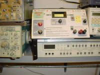
Perhaps I should explain my term "hi freq" since its really mid freq. My main load testing devices are some DIY "amplifier dynos" that have 2 frequency output settings: Lo freq (80hz) for car subwoofer amplifiers and Hi freq (1Khz) for all other amplifiers. The Cavers still seem to do well at 1Khz but I wouldn't want to go any higher.
Ok, more insults about my Fluke scopemeter. The photos were not current but I still use that same scope 99% of the time. Its really not the POS everyone thinks it is, this baby is the Crown Jewel of my work bench. The first scopemeter Fluke made, and everyone knows they cut corners on later models. I'm now just starting to break-in the Hi-Res LCD, thats why you can't see the "pip" on the old photos.
No luck in finding the thermal images I saved on CD. Give me a few days and I will scan another m400 cube and possibly another m1.5 and post the thermal image.
You seem to be one of the few Techs that really understand the Carver topology, I've picked up a few good tips from some of your past posts.
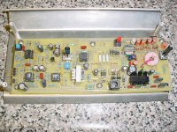
Photo is of the DIY "amp dyno" anybody want details?
Todd
Perhaps I should explain my term "hi freq" since its really mid freq. My main load testing devices are some DIY "amplifier dynos" that have 2 frequency output settings: Lo freq (80hz) for car subwoofer amplifiers and Hi freq (1Khz) for all other amplifiers. The Cavers still seem to do well at 1Khz but I wouldn't want to go any higher.
Ok, more insults about my Fluke scopemeter. The photos were not current but I still use that same scope 99% of the time. Its really not the POS everyone thinks it is, this baby is the Crown Jewel of my work bench. The first scopemeter Fluke made, and everyone knows they cut corners on later models. I'm now just starting to break-in the Hi-Res LCD, thats why you can't see the "pip" on the old photos.
No luck in finding the thermal images I saved on CD. Give me a few days and I will scan another m400 cube and possibly another m1.5 and post the thermal image.
You seem to be one of the few Techs that really understand the Carver topology, I've picked up a few good tips from some of your past posts.
Photo is of the DIY "amp dyno" anybody want details?
Todd
Attachments
Hi Todd,
I'm sorry if you feel I was taking a shot of your scopemeter. I wasn't at all. I did work in a test instrument calibration facility at one time and have hands on experience with yours. I was being factual though.
As far as that class of portable LCD 'scopes are concerned, the Fluke scope meters were the best. They still do not offer the resolution of more expensive DSO products. An HP 54600 series 'scope was far better, and it's far behind these days. Your scopemeter may be enough for what you are doing. It's probably much better than what some other technicians are using. I do know it cost you a fair bit and that was money well spent if you needed portability.
Back to the Carver ....
The problem with high frequencies and this style amp is that the commutators turn on rapidly and stay on for a minimum period of time. Therefore as the frequency goes up, the commutator tends to stay turned on. It is "locked up". This has the effect of running the output stage at a far higher voltage than is was designed for. It will overheat as a result.
I could see the basic form of the "pips". It would be interesting to see what you can capture in the high res mode then.
Your amp dyno is a neat labour / time saving device. AC meter across built in dummy loads and calibrated in watts? Could be a 7106 based design.
-Chris
Chris,
Its an old design I started about 10 years ago, all analog except for the LCD meter. This is the main circuit, not shown are the 400 watt resistors, a fan and LCD display. Lower right corner is the power supply: sg3525 pwm driving a torroid core trans that provides isolated voltages for the LCD, oscillator, precision diode, analog multiplier. Upper right corner is the oscillator: low distortion 80hz/1khz sine wave that is amplified and drives a transformer, the transformer also provides an inverted phase output for bridging a stereo amplifier. Lower right is the voltage/watts conversion: precision rectifier driving a AD633 analog multiplier, output is scaled to drive a lcd display with a maximum of 1999 watts displayed. The power supply is driven from battery power, above about 100 watts the power is pulled from the load resistors so it saves the battery power. A built in fan keeps everything cool, its power is also derived from the load resistors. By using a 24v wall wart power supply to feed the unit, an internal circuit will switch the fan and pwm power supply to use the 24v power only. Thus providing only resistive loads to the amplifier under test.
Its an old design I started about 10 years ago, all analog except for the LCD meter. This is the main circuit, not shown are the 400 watt resistors, a fan and LCD display. Lower right corner is the power supply: sg3525 pwm driving a torroid core trans that provides isolated voltages for the LCD, oscillator, precision diode, analog multiplier. Upper right corner is the oscillator: low distortion 80hz/1khz sine wave that is amplified and drives a transformer, the transformer also provides an inverted phase output for bridging a stereo amplifier. Lower right is the voltage/watts conversion: precision rectifier driving a AD633 analog multiplier, output is scaled to drive a lcd display with a maximum of 1999 watts displayed. The power supply is driven from battery power, above about 100 watts the power is pulled from the load resistors so it saves the battery power. A built in fan keeps everything cool, its power is also derived from the load resistors. By using a 24v wall wart power supply to feed the unit, an internal circuit will switch the fan and pwm power supply to use the 24v power only. Thus providing only resistive loads to the amplifier under test.
Attachments
")
hi chris
new to diy audio
i have the carver reciever which was a gift from my wife many years ago and has sentimental value. i also have a carver m400 which has a nice small footplate to fit in a liftbox for my plasma screen. i have read many of your comments in many threads regarding carver amplifiers. i have found them to be informative ,responsive, and profoundly knowledgeable. from these and others i have deduced that i lack the ability to even attempt to repair these. i cannot find any local audio technicians to fix these and the only factory solution is in oregon usa. i live in western pennsylvania usa and was wondering if you know of a local or more regional interested and competent party able to help.thank you for your time. jim
Hi Jim,
I hate being unable to answer that question for you.
In Canada, not many warranty shops could measure up. Just a couple were kept open. I had no contact with the US service network at all.
Having said that, shipping within the borders of the United States is not expensive, and it's pretty quick. Unless you know of a really good audio service shop, you should probably ship them off to Oregon for service. Be sure to call them first for an idea of charges. Make sure you have the serial numbers ready along with the model numbers.
What was the model number of your receiver?
-Chris
PCB board drawing for PS capacitors
I am interested in obtaining at least two of the PCB boards for the replacement power supply capacitors shown in a photo by Toddyaudio above. I am a new member, so I am not able to send an e-mail yet. Please let me know how I might obtain some.
I am interested in obtaining at least two of the PCB boards for the replacement power supply capacitors shown in a photo by Toddyaudio above. I am a new member, so I am not able to send an e-mail yet. Please let me know how I might obtain some.
Hi wrthissell,
Welcome to DiyAudio then!
All we can do is hope toddyaudio can see your post. He would then respond to you.
This all happened a while ago now in this thread. I am thinking that the project that toddyaudio built to test amplifiers would be a really nice project thread.
Now, with respect to replacing those capacitors .... It shouldn't be too difficult to remove the old caps. After this is done, place cardboard or paper on one side of the PCB and mark the location of the holes through the PCB onto that material. Then you only need to identify each connection. After that is done, you might want to make a copy of your terminal location guide. Now you are ready to select some capacitors and lay out where they will go, marking their terminals as well. Then, it's "connect the dots" time. Now you have a layout for a PCB. Select some blank PCB and cut it to the correct size, then use a copy of you layout to mark where the leads are going to go. Drill, clean and use a resist pen (I think it's bluing ink) to create your pads and traces. After the lacquer (or ink) dries, etch it in a bath of ferric chloride. That should only take about 15 minutes, faster if you warm it up and agitate the liquid a little. Rinse with water, remove the coating and assemble your adapter PCB.
Remember that capacitors can get pretty warm in operation, so allow space between and around them if you possibly can. Use the 105 ° types. If you can get these values in capacitors designed for switching power supplies, they may work better in this application.
Finally, there is a short moderation period for all new members. Yours will be over soon enough. Just post as you normally would until then.
I hope that helps you some. Let us know how you do.
-Chris
Was wondering if anyone knows about Jensen 4 pole electrolytics. I'm trying to replace the 4 pole 2200uf power supply capacitors on the Carver M1.5t using the Jensens. Little confused on the wiring. The Computer Technology capacitors used originally were made with their circuit layout exactly as the circuit board dictates. Would I have to cross wire the Jensens (long leads, strink tube, etc) to match what I'd need for them to be used on the board?
Hi, What did you end up doing on that?
I guess the thread was stopped.
or
did the thread move?
I"m having problems with an 1.5. Go figure.
I do have some notes with production problems
that need to be addressed with this amp.
I don't have the theory manul or the general op manual, are they available?
Cheers
I guess the thread was stopped.
or
did the thread move?
I"m having problems with an 1.5. Go figure.
I do have some notes with production problems
that need to be addressed with this amp.
I don't have the theory manul or the general op manual, are they available?
Cheers
Fix for power supply capacitor replacement Carver M1.5t
I made a power supply capacitor daughter card. I am attaching a pdf and a paint shop pro file of its design. I used a laser printer (HP, Brother did not work because of toner formulation) to print and a laminator modified for higher temperature use to transfer the image to a blank copper printed circuit board.
Here are the relevant parts I ordered from Digi-Key with prices from 2009:
Index,Quantity,Part Number,Description,Customer Reference,Backorder Quantity,Unit Price USD,Extended Price USD,
1,10,P6686-ND,CAPACITOR 6800UF 50V ELECT TSHA,,0,4.26600,$42.66,
2,10,P7509-ND,CAPACITOR 3300UF 80V ELECT TSHA,,0,4.98300,$49.83,
3,32,6A4DICT-ND,RECTIFIER SILICON 400V 6A R-6,,0,0.39000,$12.48,
4,16,565-1741-ND,CAP 330UF 100V ELECT KZE RAD,,0,0.80600,$12.90,
5,2,182-1003-ND,PAPER TONER TRANSFER, 10 SHEETS,,0,13.80000,$27.60,
6,1,182-1021-ND,FILM GREEN TRF 8"X 15',,0,8.95000,$8.95,
7,1,182-1022-ND,FILM WHITE TRF 8"X 15',,0,8.95000,$8.95,
8,3,PC52-ND,PCB COPPER CLAD 4 X 6" 2 SIDE,,0,8.29000,$24.87,
I used the PCB with the thickest layer of copper. This caused heat transfer difficulties with the laminator. I recommend backing off to the second thickest available layer.
Below are the parts I used to modify the laminator, from Digi-Key:
317-1468-ND THERMOSTAT 150 DEG C N/C FASTON (Manufacturer Part Number: R2015025)
317-1139-ND .98000 4.90 T THERMAL FUSE 192C 10A AXIAL (Manufacturer Part Number: SDJ1 DF192S)
I used the GBC HeatSeal 9" Creative Laminator - 1701987 PN:1701987 from MyBinding.com
This design requires pins and pin sockets to attach to the existing Carver printed circuit board. I used pins from Mill-Max.com:
REQUESTED P/N: 6142-0-00-01-00-00-33-0 REQUESTED QTY: 50 pcs
SENT P/N: 6142-0-00-80-00-00-33-0 SENT QTY: 50 pcs
REASON FOR PN/QTY CHANGE: Requested Plating Not in Stock
50 pcs Y
2 REQUESTED P/N: 0433-0-15-01-03-01-04-0 REQUESTED QTY: 50 pcs
SENT P/N: 0433-0-15-01-03-01-04-0 SENT QTY: 50 pcs
50 pcs Y
3 REQUESTED P/N: 3044-0-15-01-23-01-04-0 REQUESTED QTY: 50 pcs
SENT P/N: 3044-0-15-01-23-01-04-0 SENT QTY: 50 pcs
50 pcs Y
4 REQUESTED P/N: 9324-0-15-01-23-01-04-0 REQUESTED QTY: 50 pcs
SENT P/N: 9324-0-15-01-23-01-04-0 SENT QTY: 50 pcs
50 pcs Y
I looked at several of the above pins, but I used the largest diameter ones from the above selection.
I also changed the 50 and 80 V diodes from 3 Amp to 6 Amp ones.
I hope this information helps you get your amp working. I have two, and they have worked fine since I made the repairs.
Be forwarned that a bad capacitor in the power supply will likely take out a few of the control transisters on the power amp boards. This will be a pain to figure out which ones to fix. I recommend putting some heat sinks on the ones at the top of the boards about 1/3 from the left side of the amp with the front facing you.
PDFs for the service manual are available elsewhere on this forum.
Okay,
Thanks for the info.
I do have the PM 1.5 amp that was given to me.
I don't know if the tranny is fried I'll have to measure it, when I first tryed to measure it I got about 12 - 18 mOhm reading across the green primaries.
Maybe there is hope.
According to the manual, I'm supposed to have a variac, and after pulling
the protection LED, to short the triac, then with small voltage 20 - 30 VAC
check to see if the IC1, IC2 and the DIAC are enabling the Triac to turn
on.
I guess I see why many of these fried...they didn't use a viariac and
it ran away thermally.
Okay that is all for now. Did you have those PS cards made for you and
are they available?
I think I will need one.
Cheers,
Sync
Capacitor daughtercard for Carver M1.5t
I designed the board with a pdf that I attached, using Express PCB (Google for download), ordered the parts and laminator with previously supplied part numbers, ordered the chemicals to make the PCB, and I made two PCBs for my amps. I am unable to attach the Express PCB file because it is not one of the supported file types for this discussion group. I also edited the file using Corel PaintShop Pro XI, and that is another file type not supported by this discussion group.
I designed the board with a pdf that I attached, using Express PCB (Google for download), ordered the parts and laminator with previously supplied part numbers, ordered the chemicals to make the PCB, and I made two PCBs for my amps. I am unable to attach the Express PCB file because it is not one of the supported file types for this discussion group. I also edited the file using Corel PaintShop Pro XI, and that is another file type not supported by this discussion group.
I am unable to attach the Express PCB file because it is not one of the supported file types for this discussion group. I also edited the file using Corel PaintShop Pro XI, and that is another file type not supported by this discussion group.
Can you just save it as a Jpeg?
When you go to save it, at the bottom of the screen where the file name is
should be a place where when you put your cursor in it, you can scroll and change the file type. I hope that helps. I have an Old version of PaintShopPro
and if you don't edit the file, just open then try save as...see if that is an option
for you.
cheers.
Hi fellas,
If you can save the PCB layout as a PDF, the size will be preserved. That means it can be printed onto the toner transfer paper used for laser printers. I can assure you that the finished quality is very good once you figure out the heat setting on your iron, and the pressure you need to apply. Yes, I use an iron for clothing. Since I recently had my right wrist operated on and was still able to produce really good boards (for smt parts yet!), I am confident that this will work for the majority of people. Once you get this working, it opens up an entire world of high quality PCB making for your own projects.
Being far behind the times, my PCBs were designed using Acrobat Photoshop. I determined the dimensions by printing some test lines on paper and matching those to the lead spacing I needed. Extremely low tech, but it works well. After figuring out the pad layout, I cut and paste what I need to the board design. You younger folks ought to be able to do better than I did.
Hi SyncTronX,
The most common way people destroy those mag coils is by shorting out the triac and applying power. This does hideous things to the poor amp. Mag coils work on the idea of current pulses to supply the amount of energy needed. It does not operate like the transformer you may be used to seeing. It will draw high current with all the secondary leads disconnected and supplied with normal voltage, 60 Hz sine waves. That high draw is absolutely normal under those conditions. If you short the triac (or it is shorted), do not exceed 70 VAC with a variac. In fact, you can test the amplifier at much lower voltages and find most faults. Try 40 VAC for starters. The mains current draw at this level should be very low. I can't remember what the secondary voltages are at this level. It's not really important to know for the testing you are doing.
Good luck with it, Chris
File Attachments
I do not see the attachments I thought I previously attached, so I am attaching them again. Two of the files, the Corel Paintshop Pro XI file and the actual pdf file, exceed this forum's upper file size limit of 193 kb; one file is 3.45 MB. I recommend increasing the file attachment size limit to 5 MB. The file I attached is the Express PCB file. Remove the .pdf and make the extension .pcb. The pdf file I want to attach (it is 280 kb) needs to be folded over the printed circuit board and very carefully aligned so that the two sides line up. Please make sure that the file I attached is the correct one. My first try resulted in a mirror transform of what I needed, so I had to try again after I went through the entire process of making the board (ugh!). I did this three years ago, and in the process of recovering my files from a failing hard drive, all of my file dates got reset to one date. So, I am guessing which file I am attaching by file naming version control.
I do not see the attachments I thought I previously attached, so I am attaching them again. Two of the files, the Corel Paintshop Pro XI file and the actual pdf file, exceed this forum's upper file size limit of 193 kb; one file is 3.45 MB. I recommend increasing the file attachment size limit to 5 MB. The file I attached is the Express PCB file. Remove the .pdf and make the extension .pcb. The pdf file I want to attach (it is 280 kb) needs to be folded over the printed circuit board and very carefully aligned so that the two sides line up. Please make sure that the file I attached is the correct one. My first try resulted in a mirror transform of what I needed, so I had to try again after I went through the entire process of making the board (ugh!). I did this three years ago, and in the process of recovering my files from a failing hard drive, all of my file dates got reset to one date. So, I am guessing which file I am attaching by file naming version control.
Attachments
- Status
- This old topic is closed. If you want to reopen this topic, contact a moderator using the "Report Post" button.
- Home
- Amplifiers
- Solid State
- Carver m1.5t (Attn: Anatech)