
Hi
I would like one service manual too.My amp.is down for some time now and a manual will be very helpful.
Please mail to vyju@airtelmail.in
Regards
Rajiv
I would like one service manual too.My amp.is down for some time now and a manual will be very helpful.
Please mail to vyju@airtelmail.in
Regards
Rajiv
I have it on my schematic download page:
http://www.audio-circuit.dk/Schematics/Carver_PM_1.5_om.pdf
")
http://www.audio-circuit.dk/Schematics/Carver_PM_1.5_om.pdf
Carver PM1.5
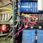
This resistance burned. I do not know it how many ohms. can somebody tell it? email: proksa1@pr.hu
This resistance burned. I do not know it how many ohms.
can somebody tell it? email: proksa1@pr.huAttachments
still can't find a service manual/schematic
HI Gang,
I still can't find a service manual and/or a schematic for the M1.5T or PM1.5.
Does anyone out there have a pdf they could email me please and thanks?
The one listed in the above post doesn't have the schematic.
Cheers
Paul
radioboy at telus dot net
HI Gang,
I still can't find a service manual and/or a schematic for the M1.5T or PM1.5.
Does anyone out there have a pdf they could email me please and thanks?
The one listed in the above post doesn't have the schematic.
Cheers
Paul
radioboy at telus dot net
Hi Paul,
The link above on ACD's site has that schematic, and a couple more. A Carver amplifier may differ slightly in the details, but they generally look the same by the schematic. One notable departure from that is the PM 2.0t and then later amplifiers where there is a lot of variance from the way they used to do things.
Your amplifier is one of the very similar group.
Where are you located again?
-Chris
Edit: ACD, thank you very much for posting these schematics up on your very helpful site. You do have some links that seem to be broken. They appear to default to the same page, but I can't remember which ones they are off-hand.
PM1.5 Switch-off thump
Hi guys,
Sorry for the thread hijack but given there are already many threads on these Carver amps it seemed silly to start a new one and this is the most recently active.
I've got a pair of PM1.5's here which I've repaired some fairly straightforward faults on. One had blown output devices and bias chain due to a speaker wiring error, the other had just been attacked by a hamfisted tech with an over-sized soldering iron!
Anyway, one of them suffers from a fairly large negative spike on switch-off. It appears on both channels but is significantly worse on one channel than the other. Op-amps have been changed and ruled out as the cause. The service manual mentions uneven collapse of the +/-12V supply which does happen but then again it also does on the other amp which has only minimal switch-off thumps.
Does anyone have suggestions as to where to look?
The +/-12V regulators have some wierd pull-ups/downs/bypass resistors between the supply rails which look like they could cause such issues but it's also possible for the amp to work fine with them so I'm puzzled!
Cheers,
Chris
Hi Chris,
There are a lot of temperature issues with these amplifiers on the "mother board", back near the mag coil area. Plan to tear down and rework everything the "ham fisted tech" touched. If you see any areas with excess solder, remove the excess or all of it. To redo a solder joint, remove the old solder before applying new solder. I clean the component leads and use liquid solder flux (for electronics!!).
Uneven 12 V rails will also do the same thing. I think there might have been bulletins that dealt with this issue. The suggestion was to change the values of the bleeder resistors. Also, mount them off the capacitor pins if you ever see that.
Their are some other issues with these amps I believe. Look in the rear of the service manual, that's where the engineering change orders live in Carver land.
-Chris
There are a lot of temperature issues with these amplifiers on the "mother board", back near the mag coil area. Plan to tear down and rework everything the "ham fisted tech" touched. If you see any areas with excess solder, remove the excess or all of it. To redo a solder joint, remove the old solder before applying new solder. I clean the component leads and use liquid solder flux (for electronics!!).
Do these amplifiers still have their original dual section capacitors? They are for the lower two supply tiers. You must replace these parts before trying anything else. One bad section would cause your problem.Anyway, one of them suffers from a fairly large negative spike on switch-off.
Uneven 12 V rails will also do the same thing. I think there might have been bulletins that dealt with this issue. The suggestion was to change the values of the bleeder resistors. Also, mount them off the capacitor pins if you ever see that.
Their are some other issues with these amps I believe. Look in the rear of the service manual, that's where the engineering change orders live in Carver land.
-Chris
Hi Chris, thanks for your thoughts.
The low voltage caps have been replaced. One amp had been done already and I've done the second one. The one with the issues has 3300uF on the 36V rails and 4700uF on the 76V rails. Under normal running the +/- 12V rails are quite even.
It does look like the 12V regulators and the wierd resistors around them could well be causing the issues but I don't really want to start redesigning the power supply in case there was a very good reason for doing it that way.
Luckily the attack by the hamfisted tech was fairly localised and mainly involved replacing the Op-Amps badly, leaving solder bridges, wondering why it no longer worked and giving up on it!
As has been mentioned on other threads about these amps, the lower supply rails seem to collapse quickly then somehow be recharged somehow from the higher rails.
I have checked the service bulletins in the version of the manual I have but they many deal with sensitivity changes, noise pickup reduction etc. Nothing mentioning switch-on/off thumps.
Incidentally, replacing the 470uF electrolytic to ground in the feedback network cured the switch-on thump but does nothing to help the switch-off.
It's also curious that one channel seems to suffer much worse than the other which makes me think it's not so much a power supply issue.
Chris
I'm still puzzled. The reason for the problem is most likely that the +36V (and thus the + 12V) collapses very quickly on power-off but the -36V and -12V collapses slowly. The switch-off thump is in the negative direction which fits with this.
How to solve it is a completely different matter however.
Why would anyone put resistors between the rails on one side of the amp and not the other. On switch-off the -36V rail continues to be fed by a 3.6k resistor from the -125V reservoir caps. There is also a 6.8k resistor going from the -125V rail to the -11V rail. But on the positive side there is just a 470R resistor which bypasses the 12V regulator for some reason. All very odd....
Hi Chris,
I'd have to examine that schematic again to better answer your question. However, they did try to make the loads even on both polarities so that the supplies would discharge evenly. Sometimes that meant a load was installed in the form of a resistor. If there is anything wrong with your supply capacitors, expect turn off noise.
The normal approach would be to install a relay to connect the speakers. A timed turn on and instant turn off would eliminate these noises. The other way to deal with it would be to have the voltage amp stage remain powered as the rails supplying output current died more quickly.
Lastly, some models of Carver amp ran each channel out of phase to make bridging easier, and also to load each polarity of supply voltage evenly.
-Chris
My suspicions are that at the time of building, higher value power supply caps were too big or expensive to use for the lower voltage rails. The resistors bleeding from the -125V rail back to the -36V and -12V rails may have been to try and make up for this and hold those rails up until the higher ones had collapsed.
Now I've fitted slightly larger smoothing caps, these resistors are no longer required as there is enough storage in the lower voltage rails own reservoir caps.
I've removed the ones on either side of the -12V regulator and the amp is now entirely silent at switch-off compared with a huge thump before.
Hi Chris,
I can't say that I have ever had a problem in that area of these amplifiers.
Just make sure you didn't remove the power supply sensing in the protection circuit! They did sample each supply voltage, including the 12 volt rails. Those resistors you are talking about would not have passed enough current to do what you are thinking.
Right now I am suspicious you have disabled the protection for supply rail detection. That is the only thing that I can think of that would connect the resistors anyway close to what you are describing. My advice would be to check that the values have not drifted and re-install those parts. I'm just running off memory right now.
-Chris
- Status
- This old topic is closed. If you want to reopen this topic, contact a moderator using the "Report Post" button.
- Home
- Amplifiers
- Solid State
- Carver M-1.5t schematic