@:Jaddie: So many negative words, so little contribution to the discussion. You are just wrecking the SNR of this thread. As such I am going to have to put you on ignore unless you can actually be postive. We have no idea who you are other than you popped up and are now p*ssing on this thread without helping. As such unless you get some kick from disrupting this thread you are wasting your time.
I would think a dose of reality, and pulling things toward actual science and away from mythology would help.
With this post, you, at least, have defined the character of the thread, and what seems to me, the attitude of the forum. I would think science and electronics would be paramount to a DIY group. Yet when I ask for data, test results, heck, even a reference...I get nothing.
Does it matter who I am? I'm here, right? So I must have an interest. I've spent hours on posts, does that mean anything? Judge from my content if I'm an idiot, a nay-sayer, or whatever. I'm not saying the postulated mechanisms are untrue, am I? I'm simply asking for verification.
Sorry I to a shot at one of your heroes, but there was no defense. Interesting that even he has moved on, with this paragraph in the Stereophile article after he discussed the Crabbe Tests,
""I've mentioned this several times in print, and it's not a very popular thought! I'm not saying that moving-coils aren't better in many other respects, which they may well be. Maybe they are more linear—all sorts of factors may come into it. But this was one of the things I was somewhat worried about, when I was concerned about reproducing LPs. I don't have any LPs now!"
So ignore me if I rain on your parade, all I'm asking for is reality. I welcome anyone with an opposing view, provided it can be substantiated. I welcome anyone to prove cartridge dynamic behavior! But please...no bad science, no myth.
Unfortunately I don't have a spare cartridge to test at the moment. I remember back when I attempted to measure my G1042 for the transimpedance design on Vinylengine, with a Holmimpulse PC jig, that I did not get the classical R+jwL impedance at all, the inductance was clearly a function of frequency. I did not really try different measurement levels much at the time, I wish that I had done so.
Yes, on the face of it George's 1st set of results on this thread #28 www.diyaudio.com/forums/analogue-source/320026-cartridge-dynamic-behaviour-3.html#post5374511 show significant deviation from ideal R+jwL classic model for frequencies above about 1kHz. At 4kHz inductance appears as though it is about 30% low, and that progresses. Phase response is pretty weird too as though impedance becomes more resistive at progressively higher frequencies.I remember back when I attempted to measure my G1042 for the transimpedance design on Vinylengine, with a Holmimpulse PC jig, that I did not get the classical R+jwL impedance at all, the inductance was clearly a function of frequency. I did not really try different measurement levels much at the time, I wish that I had done so.
That's tough to explain, IMO, and could be a jig issue I suppose. George has now built a buffered jig, and said will re-post results.
On the other hand, if there is a loss mechanism proportional to slew rate, one might expect this form of impedance result for constant level f sweeps. However, George's results didn't show variance with sweep level to any great extent, which would have varied slew rate too, of course.
LD
Last edited:
Yes, that probably explains the oddities in #28, IMO.There is only little betterment with the shorter cables.
With DUT like an MM cartridge, using a passive jig is problematic, as Rin of the soundcard (10kOhm) acts as a voltage divider when Z of the DUT goes above some kOhms at high frequencies.
I built a buffered Impedance measuring jig to get around this problem. Results are very good. I’ll post tommorow.
George
And thanks for the memory jogging link, I now recall the oddities looking for the self-resonant system mechanical resonance in MMs which I think are ironed out now.
The buffers in the new jig could be switched to have +20dB and +40dB gain/attenuation perhaps ?
LD
Cartridge mfr's don't use test records that much any more.
First the early CBS test records did not have EQ, They were constant amplitude to 500 Hz (I think) and then an abrupt switch to constant velocity. Plotted with a flat preamp all you need were rulers. The source was a GR BFO rigged to switch some circuitry at 500 Hz. Keep in mind this was the 1960's. You may still be able to find those somewhere.
Today the preferred test setup is a piezo accelerometer as the exciter for the cartridge. Doesn't wear out and has well defined properties. B&K published some stuff on this 20+ years ago I think. In any case it would be easy to setup as a test and take a lot of variables out of the mix.
Both MM and MC cartridges are extremely inefficient transducers. And if you look at the magnetic fields in a typical MC cartridge the coils are far from optimal orientation. The variants with no magnetic core for the coils barely work. In the dawn of stereo Fairchild made a cartridge where the coils mimicked a cutter head. No one has done that since. The poor magnetic path also may contribute to poor linearity in the transfer of motion to output since the mag field is nonlinear through its motion.
Cutting chains are equalized using optics looking at light patterns in the disk. It effectively removes an uncertainty from the reproduce chain, however its absolute sensitivity for level is probably limited.
Having explored impedance variations as an indication of transducer issues in headphones I'm not sure how much you will learn on a cartridge. Its so loosely coupled you would need really high resolution measurements to see anything.
As for acoustic pickup through the disk, keep in mind that the tonearm can move from acoustic SPL as well so the disk may not be the mechanism for the coupling. You could test for this with a laser. . .
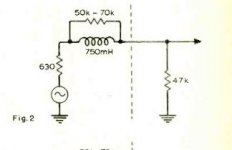
That's the CBS STR100 test record. I have one. You won't get "flat" with a flat preamp, though, because it's recorded constant amplitude from 40Hz to 500Hz. The typical curve into a flat amp is shown - attached, from the STR100 manual. The expected ideal results after RIAA EQ is also given in a tabular form.Cartridge mfr's don't use test records that much any more.
First the early CBS test records did not have EQ, They were constant amplitude to 500 Hz (I think) and then an abrupt switch to constant velocity. Plotted with a flat preamp all you need were rulers.
Well perhaps the source was a GR BFO, but it doesn't really matter. There's a 1kHz start "keying" tone, and the rate of sweep is given, so if you had a GR Type 1521A chart recorder you could run it in synch and get decent accuracy. I used a UREI Frequency Response Plotting system with the frequency tracking module, which just tracked the frequency of the input. By making an overlay of the idea result post RIAA you can resolve fractional dB excursions.The source was a GR BFO rigged to switch some circuitry at 500 Hz. Keep in mind this was the 1960's. You may still be able to find those somewhere.
Ah, there's a memory tester! Yes, sort of right, but the optical relationship is lateral velocity with a visual reflection, so you can't confirm RIAA record EQ that way, but you can make the cutter head, stylus, and driving amp flat. The optical method is pretty involved and quite interesting.Cutting chains are equalized using optics looking at light patterns in the disk. It effectively removes an uncertainty from the reproduce chain, however its absolute sensitivity for level is probably limited.
Two references: "Calibration of Disc Recordings by Light Pattern Measurements", by Axon and Geddes, July 1953, and "Optical Measurement of Recorded Velocities on Stereophonic Test Records" by C. R. Bastiaans and J. Van Der Steen, Philips Technical Review, Vol. 23 No. 3, 1961-1962.
The optical rig to do the measurements is fairly involved.
Yes. Let's do that!As for acoustic pickup through the disk, keep in mind that the tonearm can move from acoustic SPL as well so the disk may not be the mechanism for the coupling. You could test for this with a laser. . .
Edit: The reason we set up all our turntables with STR 100 is that there are too many differences between test records with RIAA EQ.
An externally hosted image should be here but it was not working when we last tested it.
An externally hosted image should be here but it was not working when we last tested it.
An externally hosted image should be here but it was not working when we last tested it.
Last edited:
I did not get the classical R+jwL impedance at all, the inductance was clearly a function of frequency. I did not really try different measurement levels much at the time, I wish that I had done so.
I've been rootling around looking for references where people have done work coming up with a better electrical model for a cartridge. First reference I have found is Reg Williamson from a wireless world letter in 1973. This is the first reference to a 'semi-inductance' with a resistance in parallel to the coil inductance.
Holmans 1975 AES paper discusses things a bit but skirts around the useful meat. He does however reference another AES paper by Hallgren which may hold useful information. Holman paper is here for those who don't have a copy.http://www.kallhovde.com/advent/phono-pre-research.pdf
Oddly (or not) MM goes out of fashion around then and very little is published for a while. Rod Elliot did some analysis around 2012 Magnetic Phono Pickup Cartridges and I've been messing around with that model to see if it gives the answers I would expect. Still no luck on that so far but spare time is temporarily short.
And one of the references Rod notes is a post from 2011 by a certain 'dlaloum' which is around the time some of the purged research was being done with LD?
Edit. Williamson model screenshot attached.
Attachments
Last edited:
Cartridge mfr's don't use test records that much any more.
First the early CBS test records did not have EQ, They were constant amplitude to 500 Hz (I think) and then an abrupt switch to constant velocity. .
I have all of them some are and some are not, in any case we can digitally produce anything we need.
You probably have not noticed that a few diehards have been through most of this over the last year or so and have posted the basic literature here, sometimes several times. We are not designing carts, this started out as tools for optimizing TT setup. Removing the playing of actual vinyl aspect totally misses the point. BTW there are miniature piezo actuators cheaply available that might work. The quartz accellerometers cost like B&K mics, $1000's for a whole set up.
The poor reciprocity of phono carts is well known and the papers were posted here long ago. Play a lateral cut groove shorting and un-shorting the pins of one channel.
EDIT - I never compared the STR-100 to the STR-130 (RIAA sweeps)
Last edited:
New the piezo accellerometers are really expensive. Second hand they are pretty cheap. Some potentially usable for as little as $25 on eBay. You will need an HV amplifier and some appropriate equalizing solution. However that's a little off topic. I was mentioning the test record issue since they are really not an economic thing to make today. however if a market for about 3000 can be found its very possible.
Assuming that the cartridge is using a Permalloy foil, the permeability plummets with frequency in the audio range:
Handbook of Modern Ferromagnetic Materials - Alex Goldman - Google Books
Handbook of Modern Ferromagnetic Materials - Alex Goldman - Google Books
Holmans 1975 AES paper discusses things a bit but skirts around the useful meat. He does however reference another AES paper by Hallgren which may hold useful information. Holman paper is here for those who don't have a copy.http://www.kallhovde.com/advent/phono-pre-research.pdf
I'm not quite sure why you'd say that, Holman actually gets directly at the "meat", but if you're interested, here's Hallgren's "improved" equivalent circuit:
Ping me privately if you'd like a copy of the paper.
An externally hosted image should be here but it was not working when we last tested it.
Holman's work is something I'm very familiar with.
While Holman focussed partly on the cartridge/preamp interface, noting the three different cartridge impedance interactions (roll off, roll up, and complex interaction with the non-flat input impedance of the preamp), he actually treats the cartridge, interface, and RIAA preamp as a complete system. This is the only effective way to deal with the complex cartridge impedance, whatever it may be, and it's interaction with the preamp.
But, as can be seen from his follow up paper, "Phonograph Preamplifier Design Criteria: An Update" from JAES May, 1980, Vol. 28 No. 5, there were still more factors to consider, such as the vinyl system's actual power response curve, transient performance, and RFI immunity. Then there's the dynamic range considerations he outlines in "Dynamic Range Requirements of Phonographic Preamplifiers" (Audio, July 1977) which considers the real dynamic range capabilities of the recorded groove as it relates to the total system.
Putting it all together, it's clear Holman wasn't concerned only with an generalized impedance model of a cartridge, or RIAA accuracy alone, but was considering everything as a complete system and engineering the preamplifier block to optimize it's role of gain, noise, and cartridge interface.
Now, that's real engineering! To be honest, it's eluded me for years as to why nobody else picked up on his design and carried it forward into today's world. It's one phono preamp that as engineered with total system consideration, and remains a work of elegance.
Yes, I think he not only hit the meat of the matter, but went clear to the bone.
His preamp circuit is published, patents long expired, it could even be built commercially with improved parts. Now there's a DIY project worth doing, perhaps letting go of matters that cannot be controlled, nor are consistent like a measurement of cartridge source impedance.
Oh, sorry...wasn't this thread about cartridge dynamic behavior?
edit: I can supply PDFs of all of the above mentioned papers if anyone wants them.
Jaddie thanks for the offer. I’ll PM you my e-mail address.
I can’t see your attached photos. I don’t know why. Is any other having the same problem?
(syntax fixed on your previous mail)
Demian, thanks for the round up. As Scott said, we have visited some (all?) of those again on other threads but it’s always good to have your knowledge and helping attitude here
George
Yes, there was a B&K paper on reverse use of accelerometer as a driver back in the day. IIRC there was a thumping big audioband mechanical resonance that had to be calibrated out.Today the preferred test setup is a piezo accelerometer as the exciter for the cartridge. Doesn't wear out and has well defined properties. B&K published some stuff on this 20+ years ago I think. In any case it would be easy to setup as a test and take a lot of variables out of the mix.
I thought of using this method in a stripped down DIY way, using other transducers (headphone drivers) but the calibration problems aren't trivial.
Ebay has enough affordable used accelerometers though.........
Agree the signals involved are tiny and require accurate handling. But in terms of flux changes in the coil, one ought to be able to observe behaviour of coil/core losses by looking at electrical impedance via cartridge pins. Reciprocity in terms of flux change induced non-ideals ought to be good, I think.Having explored impedance variations as an indication of transducer issues in headphones I'm not sure how much you will learn on a cartridge. Its so loosely coupled you would need really high resolution measurements to see anything.
One needs to generate and measure similar levels of flux change as would arise from the moving armature, which means similar level signals at the pins.
LD
Yes. One would reasonably have to ask 'why shouldn't that apply?' IMO it must.Assuming that the cartridge is using a Permalloy foil, the permeability plummets with frequency in the audio range:
Handbook of Modern Ferromagnetic Materials - Alex Goldman - Google Books
It's a small leap to level sensitivity at a fixed frequency, if slew rate of flux changes is involved in the behaviour.
LD
Assuming that the cartridge is using a Permalloy foil, the permeability plummets with frequency in the audio range:
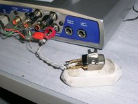
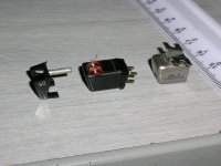
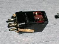
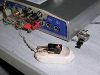
Good idea David. I will test the influence the metal shielding (don't know it's composition) may have on the impedance of this Stanton.
George
Attachments
Yes, halcyon days. David Laloum was prolific with measurements and had a seemingly endless supply of test cartridges. From which emerged a pattern of divergence which fitted a profile for level sensitive inductance and generator performance.And one of the references Rod notes is a post from 2011 by a certain 'dlaloum' which is around the time some of the purged research was being done with LD?
Edit. Williamson model screenshot attached.
The Williamson model is somewhat similar to Bill Whitlock's Jensen audio transformer model, except that the parallel resistor is non-linear in Whitlock's text. It's not expanded in the Whitlock text though, beyond hysteresis and eddy current mechanisms.
LD
Thanks, George. That will be interesting because it's said to have audible effect for some cart/coil topologies. But does Davidsrsb not mean permalloy foil laminations used in coil cores ?Good idea David. I will test the influence the metal shielding (don't know it's composition) may have on the impedance of this Stanton.
George
LD


Thanks, that's consistent both with Williamson's, and Whitlock's sketch models for real magnetics. Whitlock identifies RLT as being non-linear resistance. The devil is in the detail (and further expansion) of RLT, representing losses, methinks.The Hallgren improved equivalent circuit:

LD
- Status
- This old topic is closed. If you want to reopen this topic, contact a moderator using the "Report Post" button.
- Home
- Source & Line
- Analogue Source
- Cartridge dynamic behaviour