
Frank
Cir #3 is very similar to #2. It has a little better
PSRR ( but the best is #1) . I assumed the same cap. value
e.g. 100u , bias res 1k, tube 2a3.
Like in cir #2 the lower cap ( in parallel with bias res) see
very little current through it since the great part of the current
flows in the other cap.
In fact in post #1 I said cir #2 has a worse PSRR
Thank you Red
Finally I discover that it has also a name:.
“Ultrapath connection”
Cir #3 is very similar to #2. It has a little better
PSRR ( but the best is #1) . I assumed the same cap. value
e.g. 100u , bias res 1k, tube 2a3.
Like in cir #2 the lower cap ( in parallel with bias res) see
very little current through it since the great part of the current
flows in the other cap.
Jorge, I knowAnother drawback in the circuit 2 of your second picture is that the input pof the tube is referenced to the clean ground...and the cathode to the noisy B power suplly (virtual ground)via the decoupling cap.
In fact in post #1 I said cir #2 has a worse PSRR
Thank you Red
Finally I discover that it has also a name:.
“Ultrapath connection”
fscarpa58 said:
Jorge, I know
In fact in post #1 I said cir #2 has a worse PSRR
Conclusion!
There are no perfect solution...but some are better than others!
Salute!!
")
Hi,
When you optimise circuit #2 in such a way that the Ultrapath cap is not your PS cap but becomes a feedback cap the PSRR of the entire circuit should be far better than just circuit #1.
Then of course you'll end up with 3 caps at least...
Maybe your sim will show the result?
Cheers,
Cir #3 is very similar to #2. It has a little better
PSRR ( but the best is #1) . I assumed the same cap. value
e.g. 100u , bias res 1k, tube 2a3.
Like in cir #2 the lower cap ( in parallel with bias res) see
very little current through it since the great part of the current
flows in the other cap.
When you optimise circuit #2 in such a way that the Ultrapath cap is not your PS cap but becomes a feedback cap the PSRR of the entire circuit should be far better than just circuit #1.
Then of course you'll end up with 3 caps at least...
Maybe your sim will show the result?
Cheers,
O.K. Frank
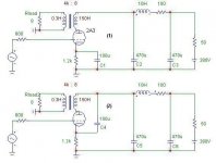
I'll start with the following circuits
#1 and #2.
SE 2A3 with 4k:8 load line, 48.5mA of static
current (VGk0=-58.5 V), Vak0 about 314V
for a dissipation of 15W.
It shows a 3.5% THD at about 2.5W
output power.
I have made a choice about working point, cap. and choke values
but I can change them as you prefer. Tell me if you want
res in series to the opt.
Federico
Attachments
Hi,
Sure, that's to be expected.
What happens in circuit # 2 is that you feedback all ripple or whatever crud is flowing there back into the cathode.
Since the 2A3 has a u of about 4 this rubbish will now show up at the tube's anode in multiplied form but out of phase.
But, what happens when we only feed the cathode 1/4 th of the PSU?
1/4 * 4 = 1
PSU rubish =1 in phase
NFB = 1 out of phase
Net result will be 0 so the PSRR should be greatly improved.
Do you see how it works now?
Cheers,
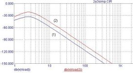
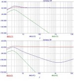
current intensity
The following figures show the current
through the capacitors in cir #1 and #2.
As one can see in cir #1 cap C1 and C2
experience almost the same current.
In cir #2, on the contrary, current
in the PSU cap (C5) is greatly reduced.
Practically, current flows only in cap.
C4 .
Federico
The following figures show the current
through the capacitors in cir #1 and #2.
As one can see in cir #1 cap C1 and C2
experience almost the same current.
In cir #2, on the contrary, current
in the PSU cap (C5) is greatly reduced.
Practically, current flows only in cap.
C4 .
Federico
Attachments
But, what happens when we only feed the cathode 1/4 th of the PSU?
1/4 * 4 = 1
PSU rubish =1 in phase
NFB = 1 out of phase
Net result will be 0 so the PSRR should be greatly improved
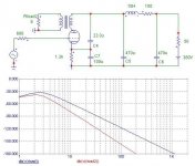
You are right, Frank
In fact circuit #3 ( as follows) behaves
very well (after a little tuning on C4)
Thanks
Federico
Attachments

fdegrove said:Hi,
Sure, that's to be expected.
What happens in circuit # 2 is that you feedback all ripple or whatever crud is flowing there back into the cathode.
Since the 2A3 has a u of about 4 this rubbish will now show up at the tube's anode in multiplied form but out of phase.
But, what happens when we only feed the cathode 1/4 th of the PSU?
1/4 * 4 = 1
PSU rubish =1 in phase
NFB = 1 out of phase
Net result will be 0 so the PSRR should be greatly improved.
Do you see how it works now?
Cheers,
Frank,
I still find it very strange. Because of the final 470uF cap on the ps side, it shouldn't make a difference where the cathode cap is connected in cir1 and cir2. Both point should be equal (zero) for AC, because of the 470uF cap. Funny.
janneman
Can you please explain, how when we feed the cathode with 1/4 of the power suplly (i presume that was 1/4 of the noise) the PSRR can be improved??fscarpa58 said:
You are right, Frank
In fact circuit #3 ( as follows) behaves
very well (after a little tuning on C4)
Thanks
Federico
When we inject noise or signal in a cathode, it will apear at the anode in phase, because in that case we have a comum grid circuit(that is no inverting)...and if it is in phase how can it cancel the power supply noise???
I thing that something is not going on...here!!
Thank you, Red
a little search and ... done.
http://www.tubecad.com/april99/page4.html
same circuit of post #29, and same behavior.
Well explained.
Federico
a little search and ... done.
http://www.tubecad.com/april99/page4.html
same circuit of post #29, and same behavior.
Well explained.
Federico
When we inject noise or signal in a cathode, it will apear at the anode in phase, because in that case we have a comum grid circuit(that is no inverting)...and if it is in phase how can it cancel the power supply noise???
Yes, it is so.
The two signals are in phase, but at the two ends of the primary of a transformer so there is no difference signal ( the difference is constant ) so no signal is transferred to the secondary.
With a trafo if the signals are in phase they cancel, if are in opposition they sum ( as in push-pull).
Federico
still find it very strange. Because of the final 470uF cap on the ps side, it shouldn't make a difference where the cathode cap is connected in cir1 and cir2. Both point should be equal (zero) for AC, because of the 470uF cap. Funny.
janneman
B+ is at near zero, not zero. They are not the same.
Federico
fscarpa58 said:
Yes, it is so.
The two signals are in phase, but at the two ends of the primary of a transformer so there is no difference signal ( the difference is constant ) so no signal is transferred to the secondary.
I see!!
But injecting another signal in the cathode ( the noise)...will increase the intermodulation distortion in the tube...
I don't know if that will give some real gains in sound quality!
And more... the noise that you are taking off the output circuity (OP transformer ) you are puting it in the input circuit (betwen grid and cathode)...
I don't know if that will give some real gains in sound quality!
I agree
too difficult to predict. Only with listening tests we'll be
able to decide.
F
fscarpa58 said:
janneman
B+ is at near zero, not zero. They are not the same.
Federico
How are they not the same? There is a 470uF between the B+ and gnd. Five times as big as the 100uF you play with. What happens if the 470uF is increased in the sim to 4700uF? Do you still have the difference? If yes, there's something wrong with the sim and not the circuit. I am very suspicious here.
Where are those graphs picked off in the post following cir1 and cir2?
Jan Didden
fscarpa58 said:
I agree
too difficult to predict. Only with listening tests we'll be
able to decide.
F

What happens if the 470uF is increased in the sim to 4700uF? Do you still have the difference?
Jan
I suppose you are referring to pics in post #28.
Yes, currents are different also in case of 4700u
... and also in case of 47000u.
Are we speaking about the same thing?
(signal) current in PSU cap of cir #2 only marginally depends
on that cap capacitance (c5) , since it has 1.2k in series with it.
In cir #1 that res. is bypassed by C1. the difference
is all here.
If I substitute C5 with a battery, the current (signal
current) in it will be always the same, also if, now,
B+ is perfectly at ground. It does not matter.
Federico
- Status
- This old topic is closed. If you want to reopen this topic, contact a moderator using the "Report Post" button.
- Home
- Amplifiers
- Tubes / Valves
- Caps topology