fscarpa58 said:Hi all
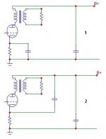
look at the following auto-bias
output stage.
It is better the pic #1 (classic)
or pic #2.
Yes it is better pic 1 lower supply noise...
PSRR is better in cir #1 but current
flows through 2 caps while
in cir #2 mainly through only
one cap.
Sorry...but in both circuits the AC current flow through the 2 caps..
")
Hi Tube_Dude
Absolutely no!
Very little AC current flows through the PSU cap of
cir #2. It is clear since that path has
more resistance ( the bias res in series) than the
other.
You can simulate it
Federico
Sorry...but in both circuits the AC current flow through the 2 caps..
Absolutely no!
Very little AC current flows through the PSU cap of
cir #2. It is clear since that path has
more resistance ( the bias res in series) than the
other.
You can simulate it
Federico
fscarpa58 said:Hi Tube_Dude
Absolutely no!
Very little AC current flows through the PSU cap of
cir #2. It is clear since that path has
more resistance ( the bias res in series) than the
other.
You can simulate it
Federico
We are at the age of simulation and people don't to put a hand and the nose in the real stuff..
Retourning to pic 2...the upper part of the power suplly capacitor(B+) is concerning AC signals a "ground"...in the pic 1 the cathod resistor is decoupled to ground...in the pic 2 the cathode resistor is also decoupled to B+ (AC ground)...
I hope i have been clear!
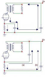
Hi Tube_dude
I completely agree, but it does not matter.
In pic #2, from the catode to B+, we can see
two paths (a and b) in parallel, as you can see in the following
pics. These paths have not the same resistance.
a) Continuous line (small res > big current)
b) dashed line ( big res > small current)
bye
Federico
the upper part of the power suplly capacitor(B+) is concerning AC signals a "ground"...in the pic 1 the cathod resistor is decoupled to ground...in the pic 2 the cathode resistor is also decoupled to B+ (AC ground).
I completely agree, but it does not matter.
In pic #2, from the catode to B+, we can see
two paths (a and b) in parallel, as you can see in the following
pics. These paths have not the same resistance.
a) Continuous line (small res > big current)
b) dashed line ( big res > small current)
bye
Federico
Attachments
Hi,
That's not true.
Look at the AC behaviour of the circuit and maybe you'll notice that circuit #2 cancels out a great deal of PS noise.
Cheers,
PSRR is better in cir #1 but current
That's not true.
Look at the AC behaviour of the circuit and maybe you'll notice that circuit #2 cancels out a great deal of PS noise.
Cheers,
In your second exemple you show the AC path from the cathode to B+ but you forget to trace the arrow through the power suplly capacitor to ground...because that AC current must be decoupled to ground...
If that path doesn't existe the cathode will be not decoupled and the circuit will have cathode feedback...
If that path doesn't existe the cathode will be not decoupled and the circuit will have cathode feedback...
you forget to trace the arrow through the power suplly capacitor to ground
Sincerely, Jorge
I do not understand what arrow.
Can you trace that arrow for me?
Are we both speaking of the current
that travel trough the tube ? true?
Frank, maybe the circuit #2
cancels out too much noise.
Yes, the noise which reachs
the catode tends to cancels out
the other but it is amplified (1+mu times)
and becomes dominant.
bye
Federico
True!fscarpa58 said:
Sincerely, Jorge
I do not understand what arrow.
Can you trace that arrow for me?
Are we both speaking of the current
that travel trough the tube ? true?
Federico
The arrow must be from B+ to ground in the power suplly capacitor...because if that path doesn't exist the tube will have cathode feedback.
Hi,
Sure, but you need to calculate what amount of PS noise you inject into the cathode in order for it to cancel out at the anode of the tube.
Assuming the valve has a u of 4 you inject 1/4 of the PS noise into the cathode for this to happen.
Ratio = C1C2/ (C+C2)
Cheers,
Yes, the noise which reachs
the catode tends to cancels out
the other but it is amplified (1+mu times)
and becomes dominant.
Sure, but you need to calculate what amount of PS noise you inject into the cathode in order for it to cancel out at the anode of the tube.
Assuming the valve has a u of 4 you inject 1/4 of the PS noise into the cathode for this to happen.
Ratio = C1C2/ (C+C2)
Cheers,
Spill the beans...
Well I've seen it called Ultrapath before, but maybe that's a misnomer.
So Frank, what is it called? And how does it differ from Ultrapath?
redwine1118 said:Hi there,
For circuit 2, is it the ultrapath connection?
Rgds,
Red
Well I've seen it called Ultrapath before, but maybe that's a misnomer.
fdegrove said:Hi,
No.
Cheers,
So Frank, what is it called? And how does it differ from Ultrapath?
Hi,
Please visit this link :
http://melhuish.org/audio/46amp.html
The diagram shows an ultrapath connection.
Rgds,
Red
Please visit this link :
http://melhuish.org/audio/46amp.html
The diagram shows an ultrapath connection.
Rgds,
Red
Hi,
Ultrapath it is...I was thinking parafeed when I replied.
Shall we open up a bottle champagne and baptise it?
Sorry Red, John,
So Frank, what is it called? And how does it differ from Ultrapath?
Ultrapath it is...I was thinking parafeed when I replied.
Shall we open up a bottle champagne and baptise it?
Sorry Red, John,
Hi,
John won't say no to a good glass of red grape juice either....
Ciao,
We should have a bottle of redwine
John won't say no to a good glass of red grape juice either....
Ciao,
 )
)- Status
- This old topic is closed. If you want to reopen this topic, contact a moderator using the "Report Post" button.
- Home
- Amplifiers
- Tubes / Valves
- Caps topology