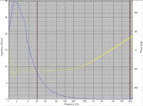
Here is a picture of a 2200µf 50V capacitor's reactance and phase response and I have a question about the phase response (yellow line). I expected the phase to remain flat at 90° across the entire frequency range but it starts changing at about 100hz. Is this normal ? I measured a 10µf polypropylene cap and the phase was indeed flat at 90° throughout. Can someone please explain what's going on ? Thanks.
P.S:- Is the peak around 2hz the self-resonance of the capacitor ?
P.S:- Is the peak around 2hz the self-resonance of the capacitor ?
Attachments
Hi,
I think the hi imp peak is a measurement artifact.
The low frequency impedance should keep rising until leakage becomes the limiting effective impedance (10s of kohms).
I am slightly surprised that you have not detected the rise in impedance by the time you got up to 20kHz. That would be more typical of electrolytics.
I think the self resonace of larger electrolytics is in the region of 10kHz to 20kHz. It is at or above this that you should see that rise in Z that I mentioned earlier.
The phase changes from 90º towards 0º as the frequency is increased because the capacitive impedance becomes so ridiculously small at high frequencies that the series resistance of the capacitor and the test fixture dominate instead.
Then, the phase continues rising towards 90º because the inductive impedance of the capacitor and the test setup is no longer negligible in comparison with the corresponding resistive impedances, and it ends up dominating at higher frequencies.
Try to reduce the resistance and inductance added by your test setup and you will get more realistic results.
Concerning the 10uF film capacitor, as its capacitive impedance is 220 times higher than in the 2200uF capacitor, the effects of parasitistic series resistance and series inductance become 220 times less important in the 1Hz to 20Khz measurement . However, you will see similar results (phase sweeping from -90º to 90º) if you measure the film capacitor between a few Khz and a few Mhz with the same setup.
This is the reason that small capacitors sound better than large ones (oops! isn't that supposed to be the other way around?).
Large values can be used if care is taken in design but going overboard is IMO discouraged. Bypassing with small value caps may create more complex resonances and can sound worse (sometimes much worse).
Large values can be used if care is taken in design but going overboard is IMO discouraged. Bypassing with small value caps may create more complex resonances and can sound worse (sometimes much worse).
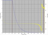
Eva, I affirm your thought that it has to do with additional resistance/inductance in the test setup. I totally removed the two leads that I connect my DUT with which are about 12-14" long each and connected the dut (cap) directly to the measuring device with a very short cable(less than 6") and the phase response certainly changed. The reactance is also more accurate now. Goes to show how longer than neccessary connections in this area affect behaviour in this area.
I am anxious to see what would be the result if this cap was bypassed by a small value (100uf ?) cap.
Notice the -180 to +180 phase shift at 11.5Khz.
I am anxious to see what would be the result if this cap was bypassed by a small value (100uf ?) cap.
Notice the -180 to +180 phase shift at 11.5Khz.
Attachments
Indm:
Please, keep your imagination under control. I only said that lower value capacitors are much easier to measure because the resistance and inductance added by the test setup is much less relevant. The impedance of a 10uF cpacitor is 220 times higher than the impedance of a 2200uF one.
Percy:
Could you explain which equipment are you employing for that measurement? Now it looks as if the impedance of the capacitor became much smaller than the output impedance of the own measurement system, thus fooling also the measurement. Is the measurement system trying to put a constant AC voltage across the capacitor and measuring the current, or is it puting a constant current and measuring the voltage?
Speaker Workshop!
Speaker Workshop, with a Turtle Beach Santa Cruz soundcard.
It has the ability to measure passive components. Its range is limited but as you can see it can measure something like a 2200µf cap with reasonable accuracy.
I believe it measures the voltage across the DUT. Look at the jig schematic that I use. That should give you an idea.
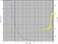
I tired a couple of different low value caps in parallel with the big electro, and lower the value of the parallel cap, better was the phase response. With the last 8.2µf polyprop cap that I tried, the phase response was almost flat to 10Khz then rose to +90° by 20Khz.
I cannot say whether lndm is right or not but it sure does raise a question in my mind - what effect would this type of phase behaviour have on the sound ? Because, agreed that these anamolies are being caused by parasitic inductance/resitance, but then again isn't this actually close to the "real world" scenario where such parasitics are bound to exist ?
Speaker Workshop, with a Turtle Beach Santa Cruz soundcard.
It has the ability to measure passive components. Its range is limited but as you can see it can measure something like a 2200µf cap with reasonable accuracy.
I believe it measures the voltage across the DUT. Look at the jig schematic that I use. That should give you an idea.
I tired a couple of different low value caps in parallel with the big electro, and lower the value of the parallel cap, better was the phase response. With the last 8.2µf polyprop cap that I tried, the phase response was almost flat to 10Khz then rose to +90° by 20Khz.
I cannot say whether lndm is right or not but it sure does raise a question in my mind - what effect would this type of phase behaviour have on the sound ? Because, agreed that these anamolies are being caused by parasitic inductance/resitance, but then again isn't this actually close to the "real world" scenario where such parasitics are bound to exist ?
Attachments
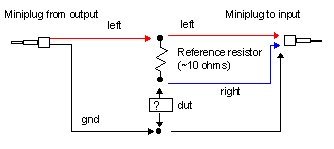
Well, the problem here is that the output amplifier of the soundcard is trying to apply an AC voltage to a 2200uF capacitor at high frequencies, and obviously it can't do that directly. Also, another problem is that due to the extremely low impedance of the 2200uF capacitor, the feedback signal turns ridiculously small at high frequencies and ends up buried in the noise floor.
Try placing a 10 to 100 ohm resistor in series with the output of the soundcard before the test fixture. Try also using a 1 ohm reference resistor instead of 10 ohms. Increasing the recording level in the recording mixer control may also help.
Try placing a 10 to 100 ohm resistor in series with the output of the soundcard before the test fixture. Try also using a 1 ohm reference resistor instead of 10 ohms. Increasing the recording level in the recording mixer control may also help.
impeadance of electrolytics
Hi Eva and Percy, I find this thread most interesting and also perplexing. It is difficult to follow for several reasons. Firstly, Eva, I greatly respect your knowledge and experience, but for the benefit of the rest of us who are trying to catch up and understand, can you please use the word 'reactance' instead of 'impedance' when appropriate ? It will make it much easier to follow you, since the discussion largely hinges on the distinction between these quantities.
Some other observations –
1) Percy's latest phase graph is characteristic of the behaviour of a parallel tuned circuit – the rapid increase in phase being the tuned freq. This needs some explaining.
2) Percy has not said what the phase is relative to. Usually a capacitor is said to have a leading (positive) phase, since engineers conventionally talk of the phase of current with respect to voltage unless otherwise stated. This is only a convention, but showing a capacitice impedance with a negative phase is confusing to an old timer like me. Is there a reason for this ? (not the confusion – the reversal of sign). If Percy has a choice it would help if he uses the voltage across the cap as the reference quantity. The phase will then turn out to be mainly positive, as we would expect.
3) The changes in sign of the phase seem to be at much lower frequencies than I would expect. I have always been suspicious of this area of audiophile mythology (as it seems to me), so I have conducted my own experiments with an ordinary 2200u/25V electrolytic. I have wired this in series with a 16 Ohm resistor, and energised it from a signal generator @ 1v peak. I observe the voltage supplied to the series combination on one channel of an oscilloscope, and the voltage across the cap on the other. Varying the freq shows the following results –
a) The two signals come into phase around 9kHz, indicating that the cap has a series resonant point around this freq.
b) increasing the freq up to 40kHz shows only a very small further advance of the phase – certainly less than 20 degrees at this freq.
c) The voltage across the cap falls as freq is increased up to around 1.8kHz, above which it gradually stabilises to a high-freq asymptote of 5mV, indicating a frequency-independent impedance of 80 milli-Ohms at high freqs. There is no indication of a rising voltage (indicating a net inductive reactance) in the freq range up to 40kHz.
d) The calculated reactance of the cap is 80mOhms at 904Hz, which is broadly in agreement with the freq at which the measured impedance begins to stabilise. This is consistant with an effective series resistance of 80mOhm.
e) Increasing the freq further reveals a very slowly rising voltage across the cap. The rise begins around 80kHz, reaching 10mV at 400kHz. Shunting the electrolytic with a 1uF foil cap reduces the voltage to about 8mV at this freq.
It seems significant to me that I have not been able to observe a region where the voltage rises with freq in the range 1k to 60kHz (say). This, and the relative ineffectualness of the 1uF foil cap raises questions about the rationality of agonising over electrolytics, except that computer-grade low esr types would be a good choice. Any comments ?
more caps
I have done some more expts with different 2,200u caps, and have found one which has a minimum impedance of 32 mOhm (2mV in my test) at 74kHz (impedance steadily falling up to that freq). The impedance of this cap then increases with freq up to a max of 112mOhm at 640kHz, after which it falls again. This cap was recovered from a switch-mode power supply, and is probably indicative of what low esr types will do.
Including just a few cms of component lead in the measuring circuit can easily double the impedance at this freq. (i.e clipping on the scope not exactly where the leads enter the body of the cap). It seems that if you are a purist you must connect the cap exactly at the point where you want the impedance to be low. Any appreciable length of connecting lead will degrade the performance of this type of electrolytic.
Hi g4oep
By "reactance" I mean a purely reactive (non resistive) impedance. Thus, you can say "capacitive reactance" and "inductive reactance".
Concerning the capacitor tests, your findings are more or less similar to mine:
1- Modern electrolytic capacitors are *not* inductive at least up to 1Mhz. They tend to be almost purely resistive between 20Khz and 1Mhz.
2- Paralelling 100nF ceramics and/or 1uF films with modern electrolytic capacitors yields *marginal* impedance reduction below 1Mhz, at the risk of dreadful ringing above 1Mhz.
impeadance of electrolytic caps
Hi Eva - I'm glad we broadly agree. I wonder why Percy is getting such odd results ?
Re reactance, resistance and impedance, the engineering understanding of these terms is -
Impedance (Z) = A complex quantity having magnitude and phase, the magnitude being the ratio of voltage to current, the phase being the phase of the current wrt to the voltage. (i.e. leading, or positive for a capacitor). Z can be expressed as Z = R + jX
Reactance (X) = the imaginary part of Z. Since this 1/jwC it is negative for a capacitor 1/jwC = -j/wC. For a purely reactive component the phase will be 90 degrees, leading for a cap, lagging for an inductor.
Resistance (R) = the real part of Z.
Typical components have Z which is mainly either real (resistors) or imaginary (inductors, capacitors), but in practice all resistors have impedances which include a small imaginary component, and supposedly 'reactive' components (inductors and caps) have a small real component, and that is exactly what we are talking about.
The variations we are discussing can be understood in terms of an equivalent circuit (as you are aware). The simplest for a cap would be a cap in series with a resistor, both elements understood to be ideal, or 'pure' forms. Leakage current requires a parallel R as well.
Sorry if this is a bit heavy. I hope it will clarify things .
ringing
' Paralelling 100nF ceramics and/or 1uF films with modern electrolytic capacitors yields *marginal* impedance reduction below 1Mhz, at the risk of dreadful ringing above 1Mhz.'
Hi Eva - I am in experimental mode again !
I wonder whether you have actually observed 'dreadful ringing above 1Mhz' or whether you are just repeating something you have heard ? I suspect this might be another myth. It is true that in the frequency range where an electrolytic cap has a net inductive reactance it is theoretically possible for it to form a resonant circuit with another, truly capacitive capacitor, but for the circuit to be oscillatory, certain conditions must be fulfilled regarding the relative magnitudes of the inductive reactance and the resistance in the circuit. I think it is exceedingly unlikely that an electrolytic could ever fulfil these requirements.
But as a hard-nosed pragmatist I have tried ! I went back to my original 2200uF cap, wired several different mylar foil caps in parallel with it (between 0.22 uf and 68nF), and excited the combination with a square wave via a resistor (I tried values between 16 ohms and 1.2k). A scope joined across the caps showed absolutely no sign of ringing at all under any circumstances. Could you suggest how 'dreadful ringing' can be demonstrated ? I am prepared to try anything, and have a well stocked junk box full of bits waiting to be tried ....
The following thread shows ringing in several flavours:
http://www.diyaudio.com/forums/showthread.php?s=&threadid=76229
http://www.diyaudio.com/forums/showthread.php?s=&threadid=76229
Hi Eva - can you give me the circuit you have simulated, re your 21 March posting ? Is this a spice (or similar) simulation ? I shall try to re-create it with real components.
I would appreciate your help with this - I might well learn something, or it is possible that a deficiency in the simulation might be revealed. Either way it would be a good thing to do.
Contact me privately if you think this thread is already getting too long.
I would appreciate your help with this - I might well learn something, or it is possible that a deficiency in the simulation might be revealed. Either way it would be a good thing to do.
Contact me privately if you think this thread is already getting too long.
That was not a simulation, that was a real PCB with a CMOS 555 timer configured as a clock and driving several CD4001, CD4013 and CD4002 CMOS gates as part of the custom control circuit of a SMPS.
The pictures are oscilloscope captures transferred to the computer and converted to GIF, not the output of a simulator.
The pictures are oscilloscope captures transferred to the computer and converted to GIF, not the output of a simulator.
- Status
- This old topic is closed. If you want to reopen this topic, contact a moderator using the "Report Post" button.
- Home
- Amplifiers
- Power Supplies
- Capacitor (filter) phase question (pic attached)