Yes.
Check how it is wired up.
It could be a CCCC supply
or
CRCRCRC, the resistors improve the ripple attenuation.
It is fairly easy to add in R between the Cs to gain that extra filtering effect.
BUT !!!
beware, 2200uF @ 450V is enormous energy storage.
Will your rectifier blow up trying to charge this cap bank?
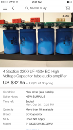
Can you read the capacitor label?
Are they 2200uF 450V ?
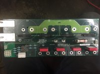
Without seeing a sch, I'm getting the impression that it has two sets of series connected caps.
Note the left pair are connected + to - and similarly the right pair are connected + to -
That makes me wonder if the four resistors are voltage balancing, indicating that the caps are not 450V but something lower.
Are they 2200uF 450V ?
Without seeing a sch, I'm getting the impression that it has two sets of series connected caps.
Note the left pair are connected + to - and similarly the right pair are connected + to -
That makes me wonder if the four resistors are voltage balancing, indicating that the caps are not 450V but something lower.
Last edited:
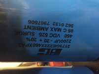
clearly 4off 2m2F @ 450V
They are old stock. Reform them, slowly to the full 450Vdc.
You can use a variac to slowly (over a perod of some hours) wind up the voltage and current limit each capacitor, using ~100k to 1M0 resistors.
You would need to remove at least three from the PCB to do this.
They are old stock. Reform them, slowly to the full 450Vdc.
You can use a variac to slowly (over a perod of some hours) wind up the voltage and current limit each capacitor, using ~100k to 1M0 resistors.
You would need to remove at least three from the PCB to do this.
you can use four limiting resistors to feed the four separate capacitors.
That way you can reform all four in the same 24hours.
Yes, it takes that long for the oxide layer to reform to minimise leakage current.
Once you have that very fine oxide insulating layer in there it degrades very slowly, if you don't maintain that reforming voltage on the plates.
But the big part is the the leakage current drops very low as soon as the working voltage falls below the reform voltage.
I don't remember the numbers, it's of the order of half leakage current for 80% of the voltage. Datasheets usually spell this out.
several years ago, i made one....
An externally hosted image should be here but it was not working when we last tested it.
Enjoy the peak current pollution they will generate.
EMI filters were installed here, besides i do not advocate this, just that the owner wanted it and challenged me to do it, who am i to say no?
")
here is another one, this time on preamps...
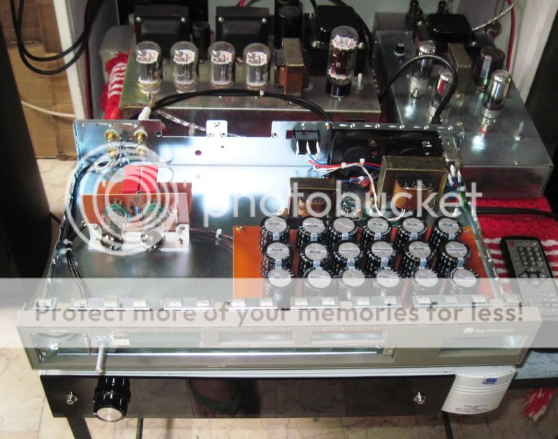
Peak current pollution? That's why I love it hear, always learning something new. I will do more research into it. Also nice setup AJT, looks lot better the mm mine
if you want to do it, be safe always....
- Status
- This old topic is closed. If you want to reopen this topic, contact a moderator using the "Report Post" button.
- Home
- Amplifiers
- Power Supplies
- Capacitor bank for ps supply filter