First, English is not my first Language.
I have an old Fender Solid State Guitar amplifier combo that is mostly used as a 1x10 Cab for a small a DIY Tube amp head with a Ragin Cajun in it. The ubiquitous Frontman 25R. After seeing the Video of Jim Lill "Where Does The Tone Come From In A Guitar Amplifier?" (
) I was thinking if I could make this SS amp usable or at least not terrible, I know that there are fans of this amps but a good tone is hard to dial, the tone is too mid scooped no wonder people play this amp with mids on 10. The clean Vol control goes from no sound at all to too much Vol between the 1 and 2 range of the Vol control. The Dirt channel is bad, really bad. Although some people like it as is. The OG speaker is meh, the easiest mod you can do is to use a better speaker, I put a ragin cajun in it. After studying the schematic I came to the conclusion that Fender made this amp to sound bad on purpose!
First let's tackle the Clean CH
This Clean Gain stage is not clean clean, it increase the high top end frequencies in the lower Vol setting, and become flatter as you increase the Vol.
The Vol control range problems can be alleviated increasing R12, I used a 18k.

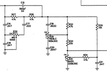
Now lets' see the Dirt CH. First we encounter a mid focused passive tone shaping. I think this is used to bring brack some of the mids that are cut in the tone stack. I practically removed the mid bump, we will fix the mid scoop later in the circuit. I entirely removed C8, C9 and C10. leaving just a voltage divider with the (22k+22k) and 8.2k.

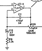
The next stage amplify just bass and mids, I want the opposite, I reduced C12 to 0.047uf to cut more bass (less fart tone) and reduce C11 to 100pf to clip more highs.

The next stage is a clipping stage, I did not understand what fender was trying to accomplish here but I changed the stage to be more like a regular soft clipping. I removed D3, D4 and shorted R23. To help reduce some of the ice pick highs I put a 100pf in parallel with R22 (470k). I needed to increase C49 and C50, I put 1uf in parallel in both. to bring back some of the bass cut in the last stage.

Both CH are then mixed in U3-A to the shared tone stack. which is the biggest problems of this amp. The tonestack is two circuits in series first a mid control which goes from a fairly scooped mids to a highly scooped mid tone too much to the point of being useless. I think that they were going for a super fendery tone. The second circuit is a two tone Bass and treble circuit . The bass is barely moving the frequency and treble control goes too high compared to the bass control. You end with no mids, few bass and too much treble. No wonder the recommended setting is mids on 10, Treble on 1 and bass on 3. That will give a usable fendery tone resembling the knowbs at 5,5,5 in a classic fender. not good. I just simply removed all of that, I put a point to point classic fender tonestack in there.

To fix the problem in the reverb, first the mix control goes from no reverb to a surf rock reverb between 1 and 3 of the control. I put a 47k resistor between the wiper and ground to simulate somewhat a logarithmic response to give more control to the mix control . I then put a B1k Potentiometer in parallel with R44 to add a Dwell control.

Lastly I decrease C24 to 100pf to let pass more highs and increased C23 to 1uf to let more bass pass. With the new tone stack those OG tone compensations are not need it. I also inserted an FX loop before R37.

All the mods make the Amp usable, more fender style, the tone is more responsive, the range of the controls are more usable and the distortion sound is more tight and focused. usable for a low overdrive or for a high overdrive for hard rock, do not expect a metal tone.
of course this will not replace my tube amp but it will sound good. I you study the schematic of the Frontman 65R and above you will see that they used the classic fender tonestack in those amps for the clean CH, so I was not so crazy. They know what sound good.
Here are the compendium of all the mods with notes, sorry for the crude use of MS Paint.

Enjoy!
I have an old Fender Solid State Guitar amplifier combo that is mostly used as a 1x10 Cab for a small a DIY Tube amp head with a Ragin Cajun in it. The ubiquitous Frontman 25R. After seeing the Video of Jim Lill "Where Does The Tone Come From In A Guitar Amplifier?" (
First let's tackle the Clean CH
This Clean Gain stage is not clean clean, it increase the high top end frequencies in the lower Vol setting, and become flatter as you increase the Vol.
The Vol control range problems can be alleviated increasing R12, I used a 18k.
Now lets' see the Dirt CH. First we encounter a mid focused passive tone shaping. I think this is used to bring brack some of the mids that are cut in the tone stack. I practically removed the mid bump, we will fix the mid scoop later in the circuit. I entirely removed C8, C9 and C10. leaving just a voltage divider with the (22k+22k) and 8.2k.
The next stage amplify just bass and mids, I want the opposite, I reduced C12 to 0.047uf to cut more bass (less fart tone) and reduce C11 to 100pf to clip more highs.
The next stage is a clipping stage, I did not understand what fender was trying to accomplish here but I changed the stage to be more like a regular soft clipping. I removed D3, D4 and shorted R23. To help reduce some of the ice pick highs I put a 100pf in parallel with R22 (470k). I needed to increase C49 and C50, I put 1uf in parallel in both. to bring back some of the bass cut in the last stage.
Both CH are then mixed in U3-A to the shared tone stack. which is the biggest problems of this amp. The tonestack is two circuits in series first a mid control which goes from a fairly scooped mids to a highly scooped mid tone too much to the point of being useless. I think that they were going for a super fendery tone. The second circuit is a two tone Bass and treble circuit . The bass is barely moving the frequency and treble control goes too high compared to the bass control. You end with no mids, few bass and too much treble. No wonder the recommended setting is mids on 10, Treble on 1 and bass on 3. That will give a usable fendery tone resembling the knowbs at 5,5,5 in a classic fender. not good. I just simply removed all of that, I put a point to point classic fender tonestack in there.
To fix the problem in the reverb, first the mix control goes from no reverb to a surf rock reverb between 1 and 3 of the control. I put a 47k resistor between the wiper and ground to simulate somewhat a logarithmic response to give more control to the mix control . I then put a B1k Potentiometer in parallel with R44 to add a Dwell control.
Lastly I decrease C24 to 100pf to let pass more highs and increased C23 to 1uf to let more bass pass. With the new tone stack those OG tone compensations are not need it. I also inserted an FX loop before R37.
All the mods make the Amp usable, more fender style, the tone is more responsive, the range of the controls are more usable and the distortion sound is more tight and focused. usable for a low overdrive or for a high overdrive for hard rock, do not expect a metal tone.
of course this will not replace my tube amp but it will sound good. I you study the schematic of the Frontman 65R and above you will see that they used the classic fender tonestack in those amps for the clean CH, so I was not so crazy. They know what sound good.
Here are the compendium of all the mods with notes, sorry for the crude use of MS Paint.
Enjoy!
Attachments
They know what will (still) sell. It's almost as if you do anything other than that particular circuit in an electric guitar amp, you're doomed.They know what sound good.
Good job on writing all that up. Maybe in that LED / diode circuit, they were trying to make it more "Zener" like. If you can find a Zener diode - or something that behaves like one - with a really low, otherwise useless Vz, those can be used in the diode clipper for more "rounded edges" on the clipped waveform.
"It's almost as if you do anything other than that particular circuit in an electric guitar amp, you're doomed"
YES, even in the Bass Amps they use the "fender circuit". Here they used fixed resistors instead of potentiometers, I believe is what makes a fender sound like fender.
This is the tone control of a Rumble V3 40w, The countour Switch change the gain of U7-C and change the mids as if you moved the mid control.
Meme; Someone picks a circuit topology / Colors a particular sound for the rest of humanities days.believe is what makes a fender sound like fender.
I wonder if you could synthesize an equivalent circuit using inductors. Not to save on production cost, but just to be different?
I have a Radio Shack graphic EQ that does this, versus the topology bass, lo-mid, high-mid topology above.
I wonder if you could synthesize an equivalent circuit using inductors.
Of course you could, that's how it always used to be done - but it's too expensive, it's cheaper to use opamps 10D/10C/11C to emulate inductors.
I have the same RS EQ. Cleaning shop I pulled the board and tossed the rest. Maybe one day I will find a project for it.Meme; Someone picks a circuit topology / Colors a particular sound for the rest of humanities days.
I wonder if you could synthesize an equivalent circuit using inductors. Not to save on production cost, but just to be different?
I have a Radio Shack graphic EQ that does this, versus the topology bass, lo-mid, high-mid topology above.
About the same plans I have for it...Cleaning shop I pulled the board and tossed the rest. Maybe one day I will find a project for it.
Too expensive for speakers too - it's cheaper to use an amplifier connected direct with a DSP in front of it. That Cu being more expensive then that Si / code.but it's too expensive, it's cheaper to use
They were accomplishing "softer", more gradual clipping characteristics.The next stage is a clipping stage, I did not understand what fender was trying to accomplish here...
View attachment 1230757
Instead of gain "folding" once to very low ratio as the diodes (including LEDs) conduct the circuit gain "folds" twice; at output signal levels below total diode voltage thresholds the gain is defined by R22, at output signal levels where a LED conducts the R23 in parallel to R22 decreases voltage gain (first fold), and at output levels where LED and diode conduct the gain is eventually "diode clipped" (second fold).
Your modification effectively made the circuit clip harder and at lower threshold.
Am I the only one who appreciates that tone control circuit for its predictabilty, range and lesser interaction?
IMHO, the classic passive Fender tone control is just awful with its totally weird control interactions that practically fail to confine the dials to work on their specific ranges of frequencies; dial treble and it adjusts mids, dial mids and the mid-notch frequency shifts, etc. And then there's the senseless ranges of the controls where the dial may have a range of -20 dB to cut and a range of only +3 dB to boost, all the while naturally interacting with rest of the frequency adjustments.
Once you get to learn it, that "unorthodox" control can do everything the passive can; but at just much greater intuition of what the control is actually adjusting. But that's just my opinion.
I also like how Fender designers went to great lenghts to design a AAIAB -style circuit when such concepts, or even concept of amp modeling, was just taking it's infant steps. The OD channel is basically modeling the classic "scooped" Fender amp with an overdriven, low-damped output section. FMIC kept using that very same recipe for their amp designs for about 30+ years all the way to the Cyber series and even the "Metalhead". The very same rudimentary design and then..
.. they were even copied by Randall in the late millennia. Randall substituting their classic high gain SS amp designs with that very same Fender circuit. Imagine that! With such track record it just can't be all that bad design, and in my opinion it really isn't. A little 25W practice platform just isn't doing the design much justice. But that's just my opinion.
Glad that you found ways to tweak the thing to your personal liking though.
Have a feeling it comes down to "do you want to sell anything, or not?" Guitarist's ears being trained on the Fender sound for so many generations, it has to go through that topology as an option, even if set in a static adjustment.With such track record it just can't be all that bad design,
The only analogy I can think of in HiFi Audio is the dome tweeter. So prevalent, so ubiquitous the consumer populace is probably dead-set on "this is what the highs on a stereo speaker sound like" / "this is what a guitar amp sounds like".
There is at least another hater of Leo's Tone StackAm I the only one who appreciates that tone control circuit for its predictabilty, range and lesser interaction?
")
I think the stock tone control circuit on the 25R is not necessarily "a problem" but I remember having to dial the Treb down almost to minimum, push the Mid all the way up, and Bass on the lower side , maybe about the same settings as InvaderLex. On the clean channel, that about got towards a "typical" Fender sound. With distortion channel, you'd be hoping the treble control could go to minus 3 to 5! So maybe it's a decent filter circuit design, but the sweep range is wonky to me. Where you expect a "neutral" Fender sound would be with pot positions at midway (5,5,5), not at the extremes of the pot range. Then you've got nowhere to further cut or boost those settings, so it's less useful. If you don't want overly scooped Fender sound, and having the Mid all the way up gets you near a Blackface sounding amp, well you're not going to be able to flatten much more than that. Has anyone played that amp with Treble on max?!!
I will test the OD with a DPDT switch to turn on and off the mod in U2-B. Originally the tone was bad to me but maybe the problem was not there but in other tone shaping parts of the circuit. I will put it on a switch and leave what sound best to me. thank you.Your modification effectively made the circuit clip harder and at lower threshold.
The TMB Fender tone stack is weird but is so old that it does not surprise.Am I the only one who appreciates that tone control circuit for its predictability, range and lesser interaction?
The same can be said about the SM57 mic. If you spend time only hearing amps recorded you can say that they sound different when you are in the room with the real thing. You can be pursuing a tone that the the amp can't not achieve alone in the room and missing the mic coloration, compression and EQ that the engineers put on the song you love. The youtuber Jim Lill explore this idea in his video "where the tone of mic comes from?"The only analogy I can think of in HiFi Audio is the dome tweeter. So prevalent, so ubiquitous the consumer populace is probably dead-set on "this is what the highs on a stereo speaker sound like" / "this is what a guitar amp sounds like".
Very good explanation of your list of mods. Just curious, does D1 and D2 act as clipping for normal level signals or just a hard limit/protection for subsequent stage?
I tested that. I removed D1 and D2 and it did not affected the tone, I put them on a switch to AB test them, and I could not hear a difference so I leave them in the circuit.
I tested that. I removed D1 and D2 and it did not affected the tone, I put them on a switch to AB test them, and I could not hear a difference so I leave them in the circuit.
Yes. Leave them as is. They are a protection against channel bleed and for the channel switch FET and have no audible impact on anything. They certainly are not "clipping diodes" in the usual sense.
Take a good look: When the channel switch FET Q2 conducts those diodes are effectively connected to the inverting input terminal of the opamp, the so-called "virtual ground", where under usual circumstances audio signal is measured in microvolts (it's a "ground"), IOW there is nothing that could be clamped to clip there.
However, when the channel is switched off by driving the Q2 FET switch to high impedance state we, in worst case scenario, theoretically would have the full output signal swing of U2A, some +/-15V, at that FET terminal. ...unless we use those diodes to clamp down that voltage to less than +/-1V of course. I wager that chance for channel bleedthrough or the FET getting damaged has now dramatically reduced from state where you pummel the FET terminal at higher voltage than its gate bias that drives the switching. Naturally you hear none of this as the channel is off.
These diodes pop up to discussion now and then and generally the theme is that people don't understand their function. There was once a "tube sound emulator" circuit featured in an electronics magazine, which was actually just a downright copy of that Fender OD channel, including those diodes although not including the channel switching. Duh. Just shameful. Alternative scenario is people clipping them off because, you know, the general frenzy to clip off every nasty solid-state diode to improve tone.
Don't. It's better off to have them there.
Thanks for the update/response!I tested that. I removed D1 and D2 and it did not affected the tone, I put them on a switch to AB test them, and I could not hear a difference so I leave them in the circuit.
Thank you for the clear explanation on that, I vaguely recalled that they may be in there as protection device and not used as a normal signal clipper. Yes definitely would want to keep them in there!Take a good look: When the channel switch FET Q2 conducts those diodes are effectively connected to the inverting input terminal of the opamp, the so-called "virtual ground", where under usual circumstances audio signal is measured in microvolts (it's a "ground"), IOW there is nothing that could be clamped to clip there.
I have a couple of suggestions regarding the drive clipping stage, if you are willing to try it out.
Re-install R23 but with a 30K to 50 K or so. Leave D3/D4 removed.
Replace R22 with a 500K Linear trimpot so you can adjust overall gain on the clipping stage to your liking.
If you remove D25/D26 clipper, install lead wires out to a small perfboard, you can test out various combinations of diodes.
Maybe use a rotary selector switch, for a few options.
One I would suggest trying is the clipper section of the Hermida Zendrive. Two 2N7000 wired as diodes and a few BAT 41 Schottkey diodes (or Germanium) in series.
That type clipper has got a really nice smooth sound, it may clip a little differently in a non-inverting op amp circuit, but I really liked
the way it behaved, you can dig in to your playing and get more crunch and bite, and then back off and get just an edge of breakup type of sound.
It definitely wasn't an "on/off" threshhold type of clipping, IMO.
Anyways, feel free to comment..this is just experimentation!
Cheers
- Home
- Live Sound
- Instruments and Amps
- Can you polish a Solid State T%rd? It seems you can