Hi Carlos!
There is one important point, which I planned different.
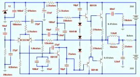
The resistor from the emitters of BC557 towards the 12V zener diode, should be around 5k6 (not 2k7 + 470).
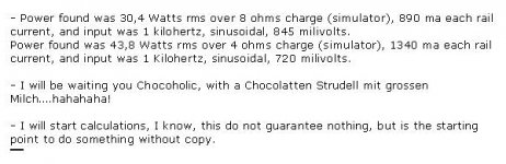
If 2k7 + 470, then you would feed a sum of about 3.5mA to the differential amp (11.3V/3170 Ohms). The current will split quite unbalanced in the differential amp. The left BC557 will run close to 1mA, but the one on the right hand side will be around 2.5mA.
Your concerns of higher Vbe:
Generally, if you go to higher current bias, then you will have higher Vbe. But this does not necessarilly indicate saturation. Saturation will happen at high Vbe and low Vce (Rule of thumb for small signal BJTs: As long as Vce is higher than 3V, don't mind about saturation). Vce in your application is around 24V...25V.
Difference in low frequency behaviour.
....probably caused by bootstrapping of VAS....
My proposal would run the VAS at higher bias, so you would also need a larger bootstrap capacitor. Please note, I already proposed 100uF+1uF (not 47uF + 100nF). In order to achieve similar low frequency behaviour as in your circuit, my VAS design would require around 270uF bootstraping .... I think....
Basically this should be defined by the time constant of the bootstrapping cap and 2k7 (in your design: bootstrapping cap and 15k)....
Difference in high frequency:
My higher bias brings down the active impedances and all the resistor values. By this it generally shifts the parasitic frequency poles towards higher frequencies.
The 47pF/68nF at the output :
...if you put it behind the output choke..... difficult combination....
In general I tend for values between 1nF-15nF.
If I can afford from side of amp oscillation, then I even tend to skip it. ...definitely one of the more difficult things, and I must admit my experience did not show good matching between simple calculations and reality, so I always optimized this on the real thing.
For this I normally start without that Zobel R-C (your 10 Ohms and 68n) network and check for various complex output loads (RLC-loads, not only R) , and then play around with different values of the Zobel for best trade off....
Good luck
Markus
P.S.
...have to go to bed now...
In 7 hours I will start for a motorbike tour through the alps , with my friends here.
...probably, I will not have WEB access the next days....
There is one important point, which I planned different.
The resistor from the emitters of BC557 towards the 12V zener diode, should be around 5k6 (not 2k7 + 470).
If 2k7 + 470, then you would feed a sum of about 3.5mA to the differential amp (11.3V/3170 Ohms). The current will split quite unbalanced in the differential amp. The left BC557 will run close to 1mA, but the one on the right hand side will be around 2.5mA.
Your concerns of higher Vbe:
Generally, if you go to higher current bias, then you will have higher Vbe. But this does not necessarilly indicate saturation. Saturation will happen at high Vbe and low Vce (Rule of thumb for small signal BJTs: As long as Vce is higher than 3V, don't mind about saturation). Vce in your application is around 24V...25V.
Difference in low frequency behaviour.
....probably caused by bootstrapping of VAS....
My proposal would run the VAS at higher bias, so you would also need a larger bootstrap capacitor. Please note, I already proposed 100uF+1uF (not 47uF + 100nF). In order to achieve similar low frequency behaviour as in your circuit, my VAS design would require around 270uF bootstraping .... I think....
Basically this should be defined by the time constant of the bootstrapping cap and 2k7 (in your design: bootstrapping cap and 15k)....
Difference in high frequency:
My higher bias brings down the active impedances and all the resistor values. By this it generally shifts the parasitic frequency poles towards higher frequencies.
The 47pF/68nF at the output :
...if you put it behind the output choke..... difficult combination....
In general I tend for values between 1nF-15nF.
If I can afford from side of amp oscillation, then I even tend to skip it. ...definitely one of the more difficult things, and I must admit my experience did not show good matching between simple calculations and reality, so I always optimized this on the real thing.
For this I normally start without that Zobel R-C (your 10 Ohms and 68n) network and check for various complex output loads (RLC-loads, not only R) , and then play around with different values of the Zobel for best trade off....
Good luck
Markus
P.S.
...have to go to bed now...
In 7 hours I will start for a motorbike tour through the alps
, with my friends here....probably, I will not have WEB access the next days....
It prevent ocsillation2) What they really stop?
Yes, my name seem like John , a english name.My name is purity vietnames name
Hello choco, you will loose a good chance, not using Bycicle today
Because using Bycicle in Alps, you can eat 3 kilograms of Chocolate without become fat!
No doubts you will return without this 3 Kilograms of chocolate and some extra weigth losted too.
But i was imagining, if Chocolate create the problem i can expect....hahahaha!, 3 Kilos huhuhu!.......can you find some plants those weather there to emergency florest WC?..hohohô...i suppose you are not in winter.... here damn cold, we are shacking, temperature now is frozen my bonds!....15 degrees centigrades!
Thanks Markus, i will do those changes and put it here in some minutes.
Carlos
Dragance, i was starting to be crazy, i think now i am completely
Complete crazy i supposed.
I decided to teach boys, a thing that i do not know, this way i am learning, studying hard and making calculations,
But i am going well, i already started to write a "book"...because if you do not now the language, you write to long,... to much..... looooooooong text.
I will do it!.... those next days i will put the easy way here, and them i will be under the bad!....because may be errors, and some people left bombs falling down, some people like strikes....but others no!.... i am doing for the others... the peacefull people, the ones can understand my efforces and forgive my errors.... and came to help.... alike you.
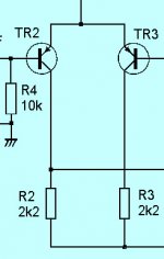
Thanks schematic, i like it very much.
regards,
Carlos
Complete crazy i supposed.
I decided to teach boys, a thing that i do not know, this way i am learning, studying hard and making calculations,
But i am going well, i already started to write a "book"...because if you do not now the language, you write to long,... to much..... looooooooong text.
I will do it!.... those next days i will put the easy way here, and them i will be under the bad!....because may be errors, and some people left bombs falling down, some people like strikes....but others no!.... i am doing for the others... the peacefull people, the ones can understand my efforces and forgive my errors.... and came to help.... alike you.
Thanks schematic, i like it very much.
regards,
Carlos
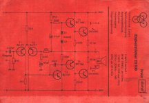
As you can see Dragance, i like it.
First because i like more "Eingang" than "input"
Will explain.... Ein means one in English... and Gang in portuguese is "group of boys", group of friends, not necessarily bad boys!.... so...... means "one group" to me....my crazy language.
But "input" is really bad......because "in" is inside, but "put" in my language means something alike "prostitute".....hummmmm, no good.... inside prostitute....hummmmm dislike, prefer not professional woman.
Also like Dragance....is a "Drag", that i can understand as Dragon, because my poor English.... also drag and drop of computer mouse....all meanings, together "ance", that remember me Flagrance, this is Perfume!....hummmmm!.... goooood!
No more chance to me.... i think i turn completely crazy....yesterday was only 50 percent crazy!
regards,
Carlos
Attachments
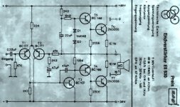
Hello Ultima thule, this capacitor is 10 picofarads
10j is the value, only to avoid oscilations, because those transistors used, BD139/140, are hi gain units... some of them goes to 175 gain.
The capacitor is conected from coletor to base, value is 0.000010uf, 10 picofards...but can be increased too.
Have one better idea?
Send to me.
regards,
Carlos
10j is the value, only to avoid oscilations, because those transistors used, BD139/140, are hi gain units... some of them goes to 175 gain.
The capacitor is conected from coletor to base, value is 0.000010uf, 10 picofards...but can be increased too.
Have one better idea?
Send to me.
regards,
Carlos
- Status
- This old topic is closed. If you want to reopen this topic, contact a moderator using the "Report Post" button.
- Home
- Amplifiers
- Solid State
- Can you please calculate this circuit