Member
Joined 2009
Paid Member
As far as I can see, the concern with XO distortion is that it is often higher order and this is the kind of distortion that gives SS amps their 'edginess' whereas lower order distortion is far less objectionable.
I assume that both ClassA and ClassB amps are capable of producing plenty of higher order harmonics so good design practices are more important that the Class of operation. However, ClassB will always have the XO distortion to worry about so if we're trying to remove the higher order harmonics Class A is in principle a better starting point.
With the proposed ClassA-G approach this XO distortion doesn't kick in until the amp is driven outside of ClassA and at this point the signal level will be higher where distortion products are increasing anyway....
I wonder if it's possible to extend the design to provide a ClassG extension for Single Ended ClassA ???
I'm with you on higher order artefacts, Bigun.
The big problem as I see it comes from the signal compression due to Vbe increases and emitter resistor losses in all PP circuits. It is these which largely create the spray of odd order artefacts beyond H3. Crossover is significan also, but I do not refer to it here. All this explains the concern with error correction feedforward.
You see this easily on a simulator. A gainblock made up of LTP front end and common emitter VAS will generate very low distortion, better than 100dB down at 20KHz into a suitable load, but as soon as you add the output stage, Class AB or Class A, the odd order harmonics spring up hugely. If it were not for global feedback, they would be 30-40dB higher again.
Nevertheless, I'm not sure ECFF is the answer either. Has anyone here heard such an amp, for example the Pax amp three months back in Elektor from Jan Didden?
Hugh
Bigun said:I wonder if it's possible to extend the design to provide a ClassG extension for Single Ended ClassA ???
But why?
 Seriously, if you're goal is to get rid of distortion, and also have some decent power when you need it, single ended is not the way to go (no offense to all the SE lovers here). But then I like my steak without ketchup.
 I think you were on the right track to start... push pull Class A with a jump to Class G.
Member
Joined 2009
Paid Member
RocketScientist said:
But why?
I think you were on the right track to start... push pull Class A with a jump to Class G.
Ah yes, push-pull vs SE is another key question. There seems to me a lot of 3rd party opinion, based on listening tests, that SE offers a sound that no other topology can match. But it's notorious for it's limitations so therefore, I wonder whether a ClassG SE hybrid could bridge the gap so to speak. I haven't discarded push-pull as the way forward but since I'm not ready to jump straight into a prototype build I want to understand what other avenues exist.
I'm not after ultra low distortion per se, but I am thinking of options that would allow me to enjoy some of the 'flavour' of low order harmonics without the 'bitterness' of the higher order harmonics. Based on reports of sterile sounding OPamps it would seem ultra-low THD is not the solution.
I must also own up and admit that I've never owned a ClassA amp, so I don't know what they sound like first hand. I may crank up the bias on my TGM amp some time to simulate a push-pull Class A at low listening levels into sensitive speakers.
Hugh - can you elaborate further on Vbe gain compression - is it something that would be visible in my sims or is it not a feature of Spice ?
Hi Gareth,
Yes, you can see Vbe compression in a simulation, but for best visiblity don't use feedback, and dispense with the front end and VAS.
So, draw up a DEF a la TGM, use a double bootstrap to set offset close to ground and create the necessary current string so as to bias it correctly, and then run a 1000K resistor from output to input, with a current probe across this resistor. That will measure uA, and correspond to 1uA/V of error between input and output.
Plot this against input voltage, up to within a couple of volts of the rail. You'll see a steadily building but non-linear error signal.
You should use an 8R load (or even 4R for worst case) to generate the high output currents where these effects are significant.
Essentially, when an output is passing 100mA of quiescent, Vbe is around 0.6V and loss across the emitter resistor is only 22mV. At around 7A, it's increased to 0.9V (2SC5200 at 25C), and this additional 0.3V loss is added to the loss across the emitter resistor, which for 0.22R would be 1.54V. So between idle and full power for a single output device and 0.22R emitter resistor, you lose (1.54 + 0.3) = 1.84V off the signal peak. To a lesser extent this also happens with the drivers. These losses are ameliorated with global feedback of course, but merely reduced by the approximate fb factor, not eliminated. If feedback factor is 60dB, it might reduce to around 2mV corrected, but it still represents odd order harmonics 80-100dB down, and it happens on peaks and on troughs. If you want to get these artefacts to -120dB or better, you need another 20-40dB of correction. Because they are odd order, they are musically objectionable, and add to listener fatigue. H2 and H3 are not too critical, but H5, H7 and beyond are definitely worth reducing.
Cheers,
Hugh
Member
Joined 2009
Paid Member
Thanks Hugh, this explains it quite clearly. Not a pretty feature of P-P. I guess any symmetric design will suffer from odd harmonics when things distort as the signal moves away from zero. A bit of asymmetry would be better if one wanted to cut down on those odd harmonics.
So a bit of thinking leads to the desire to at least explore a SE alternative. At this point it gets hard because ClassG doesn't obviously work with a SE Class A operating from the inner rails.
I also went and found something about the Self Class XD output and it seems to me that I could be heading into the same territory ? (I have long ago resigned myself to the fact that there are no virgin roads in discrete SS amps....)
Gareth,
the single-ended output is not practical for power amps, rather for headphone amps. Balanced bridge would eliminate the dirty grounds.
RocketScientist,
single-ended stages measure bad, but sound good, a bewildering mystery of linearity. What is Self saying about this contradiction? Maybe something like “You cannot manage what you do not measure.” or "If it sounds good and measures bad, it is bad." I lost trust in measurements a long time ago, thinking more like this: "If it measures bad and sounds good, then the wrong thing is measured."
Member
Joined 2009
Paid Member
Lumba Ogir said:Gareth,
the single-ended output is not practical for power amps...
If we limit it to SE only then I would agree, for the most part, that we are looking at low power amps (not exclusively, there are always exceptions). But if we add ClassG to the SE ClassA we should be able to extend the usefulness of the amp to higher powers (at the loss of the benefit s of the SE sound of course). How is to be done ??????
I lost trust in measurements a long time ago, thinking more like this: "If it measures bad and sounds good, then the wrong thing is measured."
Lumba,
By self-admission you don't know it all, but you know this clearly and I agree emphatically. The wrong thing is being measured..... but what might the X factor be if it is NOT distortion???
That is the question.
Hugh
I really don't know either....but what might the X factor be if it is NOT distortion???
might it be damping factor vs. frequency.? The famous bootstrap behaves quite differently than a standard voltage stage when driving a standard EF in this realm. The OP stage itself (triple EF vs. type 2) will sound different with different inductive loads (sub - full range). So if the OP stage and load is inaccurate ,so will be the feedback signal (same effect as self's NFB takeoff point - done wrong) , but as an amplitude and frequency dependent phenomena.
There are a few patents attempting to dynamically compensate for this (US 5796305), but triples , multiple pairs of OP's , or MOSFETS can minimize the problem. Another interesting point is "why do the cans (to-3's) sound different than the plastic OP's ? " Mike Chua from ampslab discussed this point once and it was discounted as a subjective observation. There may be truth in this ,as I heard the same effect with the cans.
This was just an observation , but I am working on how to simulate this in LT (.step LRC vs. freq) to see beforehand what a model will show. It is, however easier and more reliable to actually hear the difference in the real world
.OS
Member
Joined 2009
Paid Member
I have in the past tried simulating the speaker load as per Mr. Elliot....
http://sound.westhost.com/tsp.htm and found things got a bit nasty until I rediscovered the zobel network
p.s. never heard the difference that the cans make. That is a strange one, I can only assume a combination of capacitance differences and thermal mass (memory effect ?)
http://sound.westhost.com/tsp.htm and found things got a bit nasty until I rediscovered the zobel network
p.s. never heard the difference that the cans make. That is a strange one, I can only assume a combination of capacitance differences and thermal mass (memory effect ?)
Bigun said:I'm not after ultra low distortion per se, but I am thinking of options that would allow me to enjoy some of the 'flavour' of low order harmonics without the 'bitterness' of the higher order harmonics. Based on reports of sterile sounding OPamps it would seem ultra-low THD is not the solution.
Hmmmm... As someone who's been humbled in many blind and ABX listening tests, I can suggest all traces of "sterile" go away when you remove the psychological bias. At least they did for me. What you *can* hear in blind/ABX testing is distortion. Any significant amount distortion--even the more "musical" kinds like the 2nd harmonic.
Check out Sean Olive's blog regarding some of the cool stuff he's done with listening tests. Harman International has spent literally millions on their R&D facilities, listening rooms, etc. and Sean has been involved with subjective tests that go well beyond anything any of us can do at home.
I can also offer that a great many products rave reviewed for their amazing sound quality (and granted awards etc.) by the tweak audiophile press have those "sterile sounding" opamps in the signal path. And even some products that have extremely low levels of any kind of measurable distortion get rave reviews by the Golden Ears. So, for me, that rules out the idea of "low distortion=sterile=bad" theory. And my blind tests support that.
I can't fault someone for enjoying a particular kind of distortion with their music. Some people like ketchup on their steak too. It's all a matter of personal tastes and preferences. But one get absolutely stunning chills-down-your-spine jaw dropping good sound from a very low distortion signal chain.
If you haven't done any blind listening, or used the ABX feature of Foobar 2000 to compare things like an MP3 to a WAV file, it's worth doing. It certainly gave me an additional perspective on what matters.
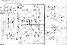
I did some research and Marantz may have beat you to it--in 1988 no less! Here's a vintage Marantz Class A/G design that uses MOSFET outputs, 28 volt inner, and 64 volt outer rails. It claims to be "pure class A" on the lower rails. I've linked a rather favorable British write up on it in Hi-Fi World and I've attached a (rather fuzzy) schematic below. Here's an excerpt from the UK review:
At normal listening levels it was an extremely sweet, clean, clear performer with an uncanny ability to let music flood forth from your speakers.
But pressed into action with a clockwise twist of its beercan-sized volume control, the velvet fist turned into an iron battering ram able to make mincemeat of the most inefficient loudspeakers. And even when forced out of its natural Class A operation, the big Marantz displayed as much grace, space and pace as a TWR Jaguar.
Marantz PM-94 Class A/G Review
If you want the PDF, let me know but the attachment size limit here prevents me from attaching it. I think it's an interesting approach to having your cake and eating it too.
Attachments
Member
Joined 2009
Paid Member
I've downloaded the schematic. The biassing is more robust and accurate than mine, although it requires more active devices.
Overall, as far as I can see, this is a good approach. There are few downsides if any, in fact the only one I can see here is some added complexity.
So that leaves me with perhaps the 'killer question'
Which do you think is better at providing ClassA performance at low signal levels but access to higher power for transients / rock-n-roll without large power dissipation...
a) The proposed ClassA-ClassG scheme
b) A Class AB amp (e.g. TGM) biassed into Class A for the first few Watts (where Gm doubling distortion is acknowledged to come into play but will be 'buried' at the higher signal levels)
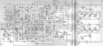
Carver 1.0t
And, since I posted the link earlier it's been bugging me... does anyone have an idea why Bob Carver used a pair of outer rail transistors feeding a single pair on the inner rail (Q127 & Q129)? See the 1.0t schematic below. It's usually the other way around (like the Marantz in the previous post).
The rail switching transistors should have an easier life than the output transistors, so am I missing something? I realize the SOA of the inner output transistors is relatively favorable. But if they can handle the current, why can't a single pair on the outer rail do the same--especially when they typically have a much lower duty cycle and are in series with the inner rail outputs.
Bob wasn't one to throw extra parts in for good measure. So anyone have any ideas? I must be missing something...
Attachments
Bigun said:Which do you think is better at providing ClassA performance at low signal levels but access to higher power for transients / rock-n-roll without large power dissipation...
a) The proposed ClassA-ClassG scheme
b) A Class AB amp (e.g. TGM) biassed into Class A for the first few Watts (where Gm doubling distortion is acknowledged to come into play but will be 'buried' at the higher signal levels)
As my math showed earlier, the dual rails will let the A/G amp idle quite a bit cooler and use significantly less electricity for the same Class A power output. I don't think a "few watts" is very practical unless you have really efficient speakers, like really low levels or only listen to heavily compressed music. A scope set to trigger in normal mode at around 2 watts into typical speakers will triger fairly often even at moderately low levels if you're listening to acoustic music.
My experience, with typical 86-89db/watt speakers is you need about 15 watts to listen to really dynamic music at moderate levels and not clip the peaks. Ever listen to Flim and the BB's?
So take that into account. If you want north of 100 watts Class B that's a lot of extra idle heat in a Class AB design.Self's data shows the gm doubling is no small problem. I agree at around 15 watts the transition it's probably inaudible. But I'm not so sure about 1 or 2 watts? So I still favor the A/G approach.
Member
Joined 2009
Paid Member
Yes ! I had missed the obvious - Good point, the power dissipation at idle is quite different between these options. It really does depend on the anticipated power level. My current DIY speakers are Fostex drivers, so they are quite efficient (in the 90's dB) but I have plans for something new (2-way or single-driver with EQ).
So the tradeoff is power dissipation verses complexity. I don't think it's fair to ask the Forum to answer that question - it may have to wait until I have determined what the amp is going to drive. Neverthess, the complexity issue is non-trivial since it's not just a few more devices but also two more power supplies if implemented as currently proposed.
So the tradeoff is power dissipation verses complexity. I don't think it's fair to ask the Forum to answer that question - it may have to wait until I have determined what the amp is going to drive. Neverthess, the complexity issue is non-trivial since it's not just a few more devices but also two more power supplies if implemented as currently proposed.
Bigun said:Yes ! I had missed the obvious - Good point, the power dissipation at idle is quite different between these options.
So the tradeoff is power dissipation verses complexity. I don't think it's fair to ask the Forum to answer that question - it may have to wait until I have determined what the amp is going to drive. Neverthess, the complexity issue is non-trivial since it's not just a few more devices but also two more power supplies if implemented as currently proposed.
Yes, that's exactly the trade off I mentioned earlier. You get Class A sound, higher power, and decent idle dissipation, but the downside is cost (and perhaps time).
One thing, just in case you're not aware of it already, a handy way to do Class G power supplies with off the shelf toroids is to series connect them. The 2nd toroid provides just the difference between the rails. So it can typically be half the VA it would otherwise need to be if it supplied the full 2nd rail voltage.
In fact, the 2nd rail toroid can be sized fairly lean (VA-wise) and it won't affect your Class A performance at all. Nor is it likely to overheat in any sane sort of use because, even with compressed music, the duty cycle on the higher rails is relatively low. If you've ever seen the transformers Carver used, he took full advantage of the low duty cycle. They were really small given the specs of the amps (and the various reviews confirmed the amps usually exceeded most of their specs at least until they shut off after a few minutes
).Of course, the best way, is with a custom tranformer. But usually 2 (or 4 for dual mono) off-the-shelf toroids are much cheaper than 1 (or 2) custom wound ones.--especially when they can both be much smaller than a single transformer would need to be.
Member
Joined 2009
Paid Member
Re: Carver 1.0t
Well a couple of thoughts.
a) the amplifier has to be able to operate at full power and don't the outer devices experience a larger Vce than the inner devices - so to keep a good SOA you want two of them ?
b) ClassAB amps often employ multiple output pairs for higher power handling, but they also benefit from additional devices in terms of lower XO distortion ?
RocketScientist said:And, since I posted the link earlier it's been bugging me... does anyone have an idea why Bob Carver used a pair of outer rail transistors feeding a single pair on the inner rail (Q127 & Q129)? [...]
Bob wasn't one to throw extra parts in for good measure. So anyone have any ideas? I must be missing something...
Well a couple of thoughts.
a) the amplifier has to be able to operate at full power and don't the outer devices experience a larger Vce than the inner devices - so to keep a good SOA you want two of them ?
b) ClassAB amps often employ multiple output pairs for higher power handling, but they also benefit from additional devices in terms of lower XO distortion ?
- Status
- This old topic is closed. If you want to reopen this topic, contact a moderator using the "Report Post" button.
- Home
- Amplifiers
- Solid State
- Can you help understand limitations of ClassA/G ?