Hello all,
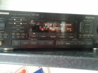
I have acquired a Pioneer VSA-730 surround amplifier. I give it power and it lights up, and changes source etc, But I get no sound. It has a main heat sink with Output Transistors mounted to it and there's two smaller sinks with Chip amps attached. These two smaller sinks heat up after a while, but no heat detected from the main amp. I assume the chip amps to be surround channels. There's a main input fuse and two more on the PSU rectifier/smoother circuit board, I haven’t delved between the various other PCBs to see if there are any more fuses, I should think relays provide further protection.
I cleaned carpets at a house the Tenant there had left it behind and the Landlord let me take it, so I don't know its history.
Is there a best practise for testing, I'd normaly check for shorts or open circuits on the output transistors, but wandered if the heating of the chip amps put the whole thing into some 'PROTECT' mode?
Your help is gratefully received, thanks.
Mike
Attachments
A best practice would be to power it up the first time with a light bulb tester to minimize damage if there is a short. However, since you passed the power up test without smoke, now its time to start from one end.
It's fairly obvious, but have you tried providing a signal to all inputs, analog and digital? Don't forget the tape monitor loop or external decoder input if there is one. Speaking of which, check that the amp is not looking at the tape loop or external decoder. I drove myself nuts one day until I noticed that my amp was looking for an external decoder.
from Fixya: Try pushing your speaker button until it says speaker A on or try pressing the button that says signal select.... push it until auto appears on the screen (You have to do this to every Input eg DVD CD etc Not the radio )
When Auto is displayed the amp will respond to whichever signal is present, analog or digital.
When pressed do the speaker select buttons result in a relay clicking?
Is there a relay click a short time after powering on? If not, it could indicate the amp is in protect mode.
Does the signal the preamp outputs? If you get there, you know that the front end is OK and you at least have a surround processor.
Beyond this stage, give the amp a good cleaning and look for signs of failed components. That will usually give you a clue where to look. A service manual will be of tremendous help, and shouldn't set you back much.
It's fairly obvious, but have you tried providing a signal to all inputs, analog and digital? Don't forget the tape monitor loop or external decoder input if there is one. Speaking of which, check that the amp is not looking at the tape loop or external decoder. I drove myself nuts one day until I noticed that my amp was looking for an external decoder.
from Fixya: Try pushing your speaker button until it says speaker A on or try pressing the button that says signal select.... push it until auto appears on the screen (You have to do this to every Input eg DVD CD
etc Not the radio ) When Auto is displayed the amp will respond to whichever signal is present, analog or digital.
When pressed do the speaker select buttons result in a relay clicking?
Is there a relay click a short time after powering on? If not, it could indicate the amp is in protect mode.
Does the signal the preamp outputs? If you get there, you know that the front end is OK and you at least have a surround processor.
Beyond this stage, give the amp a good cleaning and look for signs of failed components. That will usually give you a clue where to look. A service manual will be of tremendous help, and shouldn't set you back much.
Update
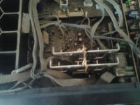
I've removed an inspection panel beneath the amplifier, and measured with a meter across the Emitter resistors and they look good at 0.5ohms. I'm not sure if I'm making a correct test of the output transistors, but switch around the three legs with the meter shows short across the outer legs, but middle leg to either outer has resistance. ??? By the way this amp has 3 pairs of Transistors. Its outputs are Front Left and Right, Left and Right rears and two Centre Channels??? There is also an Impedance selector switch!!
I've removed an inspection panel beneath the amplifier, and measured with a meter across the Emitter resistors and they look good at 0.5ohms. I'm not sure if I'm making a correct test of the output transistors, but switch around the three legs with the meter shows short across the outer legs, but middle leg to either outer has resistance. ??? By the way this amp has 3 pairs of Transistors. Its outputs are Front Left and Right, Left and Right rears and two Centre Channels??? There is also an Impedance selector switch!!
There be sound
Thanks BobEllis for replying. Three switches Front Centre Rear. Only the Centre and Rear have a click nothing from the front, however, I have audio come out of the surround speaker outputs, messing with delays, make them sound weird, I guess the delay circuits are kicking in. These outputs have small cheapy spring loaded terminals, so they must be low current coming from the chip amps, but the Front and Center have Screw/Banana terminals for 4mm jacks. I take it, seeing as no relay click, the amp is in protect mode........
Thanks BobEllis for replying. Three switches Front Centre Rear. Only the Centre and Rear have a click nothing from the front, however, I have audio come out of the surround speaker outputs, messing with delays, make them sound weird, I guess the delay circuits are kicking in. These outputs have small cheapy spring loaded terminals, so they must be low current coming from the chip amps, but the Front and Center have Screw/Banana terminals for 4mm jacks. I take it, seeing as no relay click, the amp is in protect mode........
Still check that there is a signal at the main channel preamp outputs. Pull the jumpers and plug a cable from the front outputs into the surround inputs.
Testing transistors in circuit can often lead to odd results. A dead short is somewhat suspicious, though. Are there labels for the pins on the top side of the boards like BCE or GDS? Can you read the part numbers on the output devices?
Testing transistors in circuit can often lead to odd results. A dead short is somewhat suspicious, though. Are there labels for the pins on the top side of the boards like BCE or GDS? Can you read the part numbers on the output devices?
No relay-click = protection mode!
If those chipamps get really hot - yes it might be those that are the partykillers.
You need to locate the defective channel, which will most likely have full voltage of either polarity ( +/ - 30-45 volts DC) on the output.
Start by just measuring the voltage from ground (chassis) to the Zobel network ( coil+ big resistor + cap) at the output of the chip-amps.
If none of these are defective, then locate the emitter resistors of the discretely buildt channels, and measure the voltage from any of these to ground ( chassis).
When you find the defective channel you can start replacing components.
Not much happening
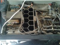
Well I checked around the Zobel on the Chip amp output, no strange voltages there, so maybe the heat sink is usually that warm, meanwhile I attached a probe to a phono sockets body for ground and my other red probe, prodded the Emitter Resistors, no voltages there!!! My output trannies are 2SC3281 and 2SA1302 with 50 volts on all centre legs, (Collector), plus/minus respectively.
Thank you
Last edited:
Heat sink warm and no voltage across emitter resistors makes no sense. Are you sure that you measured at the emitter end to ground? Measuring at the output end should be near zero whether that channel is working or not. Try measuring the emitter to emitter voltage, or at least emitter to ground. The amp is probably not class B (and wouldn't be warm if it was)
Did you check that the main channel preamps work?
Did you check that the main channel preamps work?
Hi,
Just in case you do not have the service manual here it is a link that you can down load it free.
link:PIONEER VSA-730 SM Service Manual free download, schematics, eeprom, repair info for electronics
Just in case you do not have the service manual here it is a link that you can down load it free.
link:PIONEER VSA-730 SM Service Manual free download, schematics, eeprom, repair info for electronics
True. Deafuser - although you state that there is no voltage across the emitter resistors are you looking for the low voltage that should be present. Dependant on the bias and the value of the resistors, you might only be looking for 0.1V or so. It might even be less, as an example 100mA of bias across an 0R33 resistor will only give you 0.033V.
Last edited:
Hi all
I have checked for audio by removing link and sending signal to rear channels and audio was present. I only have a basic Analogue meter at the moment. My DMM is at the Ex's house along with a lot of other stuff, I couldn't measure any low voltages across the Emitter Resistors.
Lol, I failed 3 out of 5 on that test to register to get the manual, I used my phone
If you keep failing the critical test, you can download the same manual fro FREE from HiFi Engine | Download Free User/ Service Manuals, Amplifier, Receiver, CD, Tape, Tuner, Video...
The protect circuit in this beast simply disconnects the Centre Front R and Front L amplifiers from the speaker terminals using relays. It should be a fairly simple task to see if the signal is present at the amp side of the relays using a cheap speaker and a bit of wire. Then you would know if the amps are faulty or if the protection circuits has operated because of a fault.
Check for DC offset before connecting a speaker, anything over 0.1V DC is indicative of a fault.
You can also check for audio at the place where each pair of emitter resistors connect together and to a third trace. That's the output. From your description it should be visible through the bottom panel.
You can also check for audio at the place where each pair of emitter resistors connect together and to a third trace. That's the output. From your description it should be visible through the bottom panel.
Update
Hi Everyone, I grabbed the schematic showing 2 relays, ( thanks KatieandDad), I'm think Relay 3 is headphone and Relay 5 is the Main Front? Relay 4 Centre?
Thank you
Hi Everyone, I grabbed the schematic showing 2 relays, ( thanks KatieandDad), I'm think Relay 3 is headphone and Relay 5 is the Main Front? Relay 4 Centre?
Thank you
Attachments
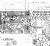
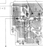
Looks that way to me. Relay 4 is L and right, 5 center. I don't recall seeing jumpers in a ground plane before. (follow the G trace from the header, there are couple jumpers in the ground plane there)
The traces at the top of the drawing are where you want to look for signal. It looks like chip amps for the main channels.
The traces at the top of the drawing are where you want to look for signal. It looks like chip amps for the main channels.
- Status
- This old topic is closed. If you want to reopen this topic, contact a moderator using the "Report Post" button.
- Home
- Amplifiers
- Solid State
- Can you advise me on a repair, please?