Thanks, Al. I was looking for an apple and you wanted me to search for an orange. My keywords were "stereo channel sum summing mono" and so forth. Still a little over my head...but I'l keep leanring 
I guess I could power this little "pre-amp inverting thingie" with the same power supply from the LM3875 power supply.
I guess I could power this little "pre-amp inverting thingie" with the same power supply from the LM3875 power supply.
Al:
Let me just make sure that I'm absolutely clear on something. If I had an amp that was configured as inverting, then I would not need this channel summing OP in front of it to combine stereo channels? It's because my LM3875 kit is a non-inverting kit that I have this complication? In your mind, would going inverting on the amp work out better?
Let me just make sure that I'm absolutely clear on something. If I had an amp that was configured as inverting, then I would not need this channel summing OP in front of it to combine stereo channels? It's because my LM3875 kit is a non-inverting kit that I have this complication? In your mind, would going inverting on the amp work out better?
I recognize that...
It's a SALLEN-KEY!!!
U can work good with it, but your cutoff frequency is not 115 Hertz in that config, but in 185 Hz.
Remembering that the -3 dB point in a Sallen-Key configuration is at the frequency
Fc = 1 / (2*pi * sqrt(R11*R12*C5*C6))
*sqrt is square root
*this is based on your second schematic (that with the buffer)
Yo could just change the resistors to 39K (cutoff frequency will be 105 Hz) or 33K (cuttoff frequency will be 123 Hz).
I would use the first , because with this values u choosed, this is clearly a BUTTERWORTH filter, and it doesnt decays so fast after the cutoff freq.
U could check the freq response on your simulator (the PSpice).
Or u could just use the passive config with just resistors and capacitors, but the freq response is worse.
Oh, and a BUTTERWORTH filter NEVER oscillates, so dont worry about that.
Hope i helped a little. ;-)
Nordic said:Speaking under correction, but the summing can be done by as simple unity gain opamp, with the left and right inputs connected to non inverted inputs trough a small 10k resistor...
You can do all sorts of things in electronics, but the results may not be optimum...
victorio said:I recognize that...
It's a SALLEN-KEY!!!
U can work good with it, but your cutoff frequency is not 115 Hertz in that config, but in 185 Hz.
Remembering that the -3 dB point in a Sallen-Key configuration is at the frequency
Fc = 1 / (2*pi * sqrt(R11*R12*C5*C6))
*sqrt is square root
*this is based on your second schematic (that with the buffer)
Yo could just change the resistors to 39K (cutoff frequency will be 105 Hz) or 33K (cuttoff frequency will be 123 Hz).
I would use the first , because with this values u choosed, this is clearly a BUTTERWORTH filter, and it doesnt decays so fast after the cutoff freq.
U could check the freq response on your simulator (the PSpice).
Or u could just use the passive config with just resistors and capacitors, but the freq response is worse.
Oh, and a BUTTERWORTH filter NEVER oscillates, so dont worry about that.
Hope i helped a little. ;-)

thanks a lot, i'll revise that part.
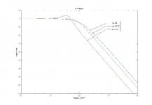
the first one was generated with R=39k, the second with R=22k.
doesn't look like the results of that formula.
i agree to that formula, but simulation shows something different.
has it got anything to do with Q? I guess the "bode" lines cross in the value given by the formula, but the real line goes way below that.
doesn't look like the results of that formula.
An externally hosted image should be here but it was not working when we last tested it.
i agree to that formula, but simulation shows something different.
has it got anything to do with Q? I guess the "bode" lines cross in the value given by the formula, but the real line goes way below that.
Hi,
expand your frequency scales to at least an octave above and an octave below the -3db turnover frequency. i.e. 40Hz to 300Hz.
An equal component value Sallen & Key uses a slightly different formula from the unity gain Sallen & Key.
The Butterworth must have Q=1/sqrt2 =0.7071
ECV S&K F-3db=1/2PiRC
UG S&K F-3db=1/2srqt2PiRC note the difference of the extra sqrt2, when the components are chosen to give the correct Q.
Oops... 
Sorry, I calculated a wrong Q for the circuit. I thougth it was 0.707, but it is 0.5, so the frequency i gave you is the -6 dB point, and the decay is worse than the Butterworth.
I recommend you to make the feedback cap (C5) aproximately 2x the C6. This way u make a Butterworth.
Just to make things clear, i attached a figure.
The freq (Fc) i gave to you is called the NATURAL FREQUENCY.
When Q is above 0.707, the freq response has a peak of magnitude 20*log(Q) in the NATURAL FREQ.
When Q is equal or below 0.707, the magnitude in the NATURAL FREQ is 20*log(Q).
* log is log of base 10
** When Q=0.707, the magnitude at the Natural Freq is 20*log(0.707) = -3 dB, and the filter is called a Butterworth filter.
*** In your schematic, with Q=0.5, the magnitude at the natural freq is 20*log(0.5) = -6 dB.
Sorry by the tons of theoretical stuff... ithougth i talked a lot
Attachments
AndrewT said:Hi,
for summing two channels you should use the opamp in it's inverting mode.
Then the virtual earth at the inverting input sums the signals coming through all the line resistors. Just perfect for a two channel into one sub...
AndrewT:
Why wouldn't the non-inverting summing circuit in Fig. 3 of the attached not work instead of the inverting scheme?
http://www.analog.com/UploadedFiles/Data_Sheets/SSM2141.pdf
Hi Carlos,
I don't understand why you have referred us to a balanced line receiver.
But, go buy a 2141 and connect your two bass channels to the two inputs and send the bass output to your bass amplifier.
I think you will find that you can manage with a 10mW amplifier and it will never overload on ordinary stereo music signals. Potentially saving you a lot of money on big sub-bass speakers and amps.
- Status
- This old topic is closed. If you want to reopen this topic, contact a moderator using the "Report Post" button.
- Home
- Amplifiers
- Chip Amps
- can this work?? subwoofer filter