I have built such modules in 2013 for my ML-1 and have them in daily use since then. I used Toshiba V grade FETs which are unavailable now. Attached is a LT-Spice simulation with FETs from Linear Systems and bipolars from Fairchild (both still available, so no risk to buy fakes). Simulation results are excellent (THD 0.000038%).
Attachments
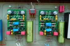
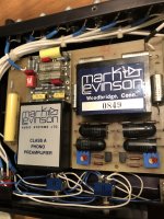
Thats what the new modules mentioned in my last post look like.
Hi, your new modules looks great!
I want to know what the fets, output transistors and resistors values you are using, could you inform with details here or by PM
Thanks,
Patrick
he listed part numbers in the LT Spice file he included.
even included models - what a guy!
mlloyd1
Thanks, mlloyd1
I installed the software and I can check the schematic.
Cheer
Well, he mentioned using Toshiba V grade JFETs in his own build.
Simulation is with Linear Systems JFETs, which has different transconductances, especially for PJFET.
The photo shows output devices as 2SA1209/2SC2911.
The Spice model uses KSA1381/KSC3503.
So I would not say they are the same, but compatible.
Cheers,
Patrick
Simulation is with Linear Systems JFETs, which has different transconductances, especially for PJFET.
The photo shows output devices as 2SA1209/2SC2911.
The Spice model uses KSA1381/KSC3503.
So I would not say they are the same, but compatible.
Cheers,
Patrick
Yes Patrick, you are correct. I looked it up and actually I have built those in 2009 and the Fets were Toshiba V grade and the output devices Sanyo 2SA1209/2SC2911.
I bought all of them from Erno Borbely at that time. All of these are not available any more.
The purpose of the simulation is to show that this could be built with parts available new today. Matched FETs are available here at the Store:
Linear Systems Matched JFETs – diyAudio Store
KSA1381/KSC3503 are available at e.g. Mouser.
Georg:
Did you even run any actual measurements on your finished design? The LT Spice sim is impressive and I'm curious to know how close the final design came. Yes, I know the parts are different; the older, original Toshiba JFETs are probably better (higher Gm, lower noise?) than the Linear Systems and the latter Fairchild BJTs are probably better (lower capacitance, higher and flatter hFE?) than the Sanyo BJTs.
mlloyd1
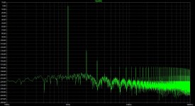
Yes, I did try some measurements but they were not really conclusive because I dont own equipment to measure that low. I used a RME ADI-2 (the old one, not the new ADI-2 Pro which has lower distortion) A/D D/A combination and the result was basically the same with the JC2 in the loop and loopback.
Attached is the screenshot which shows some 2nd and a tiny bit of 3rd. The JC-2 alone probably has lower distortion than that.
BTW in simulation the KSA1381/KSC3503 have almost 15 dB lower distortion than the 2SA1209/2SC2911.
Attached is the screenshot which shows some 2nd and a tiny bit of 3rd. The JC-2 alone probably has lower distortion than that.
BTW in simulation the KSA1381/KSC3503 have almost 15 dB lower distortion than the 2SA1209/2SC2911.
Attachments
Georg:
Thanks for your comments. In a similar thread on this site, GlenK built this preamp also when he was around. He used Toshiba V rank parts. I thought said he didn't measure a difference between using the Sanyo BJTs vs the Fairchild BJTs. I was curious to know your experience. I definitely understand the equipment limitations issue! I am still impressed by what we can measure at home today versus what we could measure at home 30 years ago!
mlloyd1
In the old days I always admired the Hewlett Packard 339A Distortion Analyser, that was the state of the art and of course unaffordable for an amateur. With this nice machine we would say "distortion of the JC-2 is < 0.001% (unmeasureable)".
I have a low distortion generator from Viktors Mickevičs waiting here for a power supply and case. With the A/D part of the RME the lower limit would be 0.00032% then. Probably still not low enough to see a significant difference between Sanyo BJTs vs the Fairchild BJTs.
Anyway, the nice things about the JC-2 are: No high order distortions, can drive about anything (long cable runs) with zero overshoot or ringing and is on par with the lowest noise Opams for SNR. Ticks all boxes for a perfect line stage I would say.
Thats what the new modules mentioned in my last post look like.
Are you selling these or the PCB s?
No I am not selling anything, I made them for my personal use in my ML-1. Do you own a JC-2 or and ML-1 that needs to be fixed ?
I have one with bad line input module. But I would like to replace both with more modern components.
Robt.
No I am not selling anything, I made them for my personal use in my ML-1. Do you own a JC-2 or and ML-1 that needs to be fixed ?
No, I've just wanted to make the modules for a long time and put them into one of my
cheap preamps. Even thought about modding one with relays to switch between amp
designs.
Very nice work by the way.
You have my permission to do what you like.
Now, there IS a difference between the JC-2 and the LMP-2 line amps. The first LMP-2's used IC's (inside the modules) and they required much less current to operate. Therefore the power supplies for the LMP2's was only 100ma. The JC-2 required a 300ma power supply. Please note LMP2's power supply capacity when making modules to suit.
Dear John,
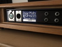
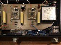
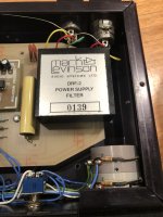
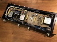
I have just bought this superb piece of equipment which is the JC-2, and even though Im enjoying it, I'm not sure about "what is actually inside it".
I'm attaching pictures of my unit, and as you can see there are 2 modules over the Phono modules and I cannot identify them. Could you please help me out?
Both line modules were made from a local company, but I might change them shortly.
Also, I can't find much information with regards to the phono section. My cartridge is a SAEC XC-10 (0.25mv output, Internal impedance 4Ω) and Im neither sure if I should use a step up or just plug it to the preamp.
Kind regards from Buenos Aires, Argentina
Fernando
Attachments
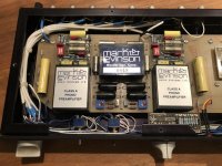
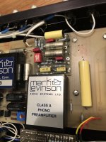
Well, I´m not John, but your JC-2 has the MC pre fitted (between the two phono preamplifiers), so you do not need a step up.
Hi Georg!
Thanks a lot for your comments and info!
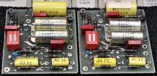
So if im not mistaken, from the image attached the module framed in green is the MC head-amp, and the modules in red are the gain/impedance modules, though im not sure if they are the D5 or D6 ones.
Since my cartridge is .25mv do you know how should I set them? I apologize for my huge ignorance in the matter
Regards!
Attachments
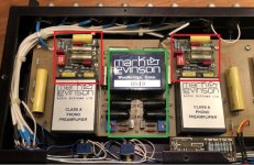
Hi,
yes the green framed part is the MC head amp. I myself dont own the headamp and have an A4E card but from the photo I guess yours is the D6 (see attachment). Normally these cards have a little sticker glued on where the type is noted.
Personally I would leave switch 1 open (CRC out).
For a nominal .25mv input 60dB (switch 2 open) will give 250mV out and 66dB (switch 2 closed) will give 500mV out. Both values are sufficient but you can try both settings to see which one is a better match for the level of your other sources. At any rate, always turn the volume completely down before operating this switch.
Attachments
- Home
- Amplifiers
- Solid State
- Can someone help with Mark Levinson JC-2?