Member
Joined 2009
Paid Member
My current SE Home Brew is good enough
Very interesting!
Are you referring to your SE Mosfet Home Brew or your SE 6V6 home brew ?
seems kinda fishy if you ask me.

SE 6V6...
But my Mosfet home brew out did the solid state amps I have.
My home brew tube amp was preferred over a new model $1100.00 Marantz when connected to the owner's Monitor Audio book shelf speakers. It was a 6L6gc driven by a 6K5gt...using RCore 120v-15v power transformers as OT's. Didn't get near as loud...but loud enough to have the wife tell us to turn it down in fear of the neighbors complaining. Crystal clear...
Same set up with 115v - 6.3v gives pretty darn good well defined bass as well.
Though, I know it shouldn't sound as good...got lucky...maybe.
I do agree with Famousmockingbird...many improper SE circuits will catch plenty of bass...when wired with nightcrawlers and using the best hand carved Rapala lures from Finland. Though I'm not sure the night crawler has the best dialectric strength...and too much absorbtion for any capacitor...
I'm checking my amp for any lures my son may have left around
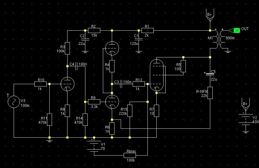
Sorry, when you said "CCS" I assumed you meant CCS. What you actually have there is a hybrid mu-follower - quite different. The right-hand CCS merely increases the current in the active load MOSFET, so increasing its gm and reducing the stage output impedance.MrCurwen said:I'm referring to the schematic I posted earlier in this thread.
http://www.diyaudio.com/forums/attac...-pp-27_71a.png
In this schematic, the plate load MOSFET can provide current very well to charge up C2, and the CCS (on the far right) can sink current very well to discharge it. Tube is relieved and operates much more linearly. The OT is better controlled by this kind of drive, and the load (speaker) is better damped. If tube is linear, no NFB needed.
All that fun stuff is packed away while my new house is being built, and I am currently using a $20 Lepai amp through Yamaha NS-10M studio speakers.
Me too, I'm reduced to a JBL Xtreme while my building work is in progress

I lowered the impedance of my SE so it had much firmer bass by removing the GNFB loop and feeding back from the output tube's anode to the driver's tube cathode. In that way I have almost limitless amounts of (fast) feedback I could play with to lower the impedance driving the primary. Sounded way cleaner than before and more dynamic, comparable to a 150WPC class A SS amp (it replaced an Usher R1.5) for general dynamics.
The main improvement I'll add at some stage is PSU line feedback to eliminate PSU noise/dips etc - to boost dynamics and reduce noise, a very overlooked subject (except at tubelab!!).
When the building work is done of course....
Last edited:
I built a 6P41S SE amp that is good for 4W triode mode and around 6W UL. Bass is better in UL mode and is quite good driving Klipsch Heresey speakers. Overall I believe bass is comparable to bass of my 12W PP amp (6P1P) driving the same speakers.
I used no global feedback in the SE amp.
I did use 15W rated OPTs (Edcor GXSE15-8-5K) which I believe helps a lot.
I used no global feedback in the SE amp.
I did use 15W rated OPTs (Edcor GXSE15-8-5K) which I believe helps a lot.
Let me qualify my own opinion. My experience is that if you use a SE amplifier well below its max power it will sound just about the same as any PP at similar power levels. In order to test this you really need very sensitive speakers of the order of +100db/W.
Shoog
Or a very, very powerful SE amp.
output tube's anode to the driver's tube cathode. In that way I have almost limitless amounts of (fast) feedback I could play with to lower the impedance driving the primary. Sounded way cleaner than before and more dynamic,
BINGO! That matches some of what I am seeing. I have shrunk the feedback loop even further. The last design I breadboarded before packing everything up had feedback directly from the output tube's plate to the network feeding its grid. I got to listen to it for about one day before stuffing it in a box. Let's just say I will be continuing my work....
Getting the OPT out of the feedback loop is important. Lowering the impedance driving the OPT is too. So is keeping the feedback loop short, and free of reactive elements.
Interesting!
I got the idea from a series of posts here by Thorsten Loesch, who was pointing out that at HF and LF a GNFB loop wasn't really working with very much gain if you stuck a transformer in the way (due to its bandpass effects), and you'd get more quality and bandwidth by driving it better in the first place. Plus one avoids pole and zero juggling to a great extent.
I also feel that just using a big GNFB loop means the transformer is (in general) driven with a pretty high impedance and then corrected later - via the same rather dodgy signal path - which can't be such a good idea for the harmonics.
I thought about a single loop around the output tube as you describe - I worried I wouldn't get enough gain for the amount of feedback I wanted to apply. I also read your articles on the issues of arranging the output tube as a follower with the added advantage of basing the signal on ground rather than the usual way of hooking up the primary to B+ and hoping it wouldn't move much. Compared to that goal a common cathode + local FB + PSU cancelling is a bit of a compromise - but much easier to build.
Certainly (as rewired) my SE had/has (it's in the loft right now) a nice open feel with huge presence, even with the OPTs that I used which couldn't have been that great given the budget-Chinese-ness of them! It really sounds/ed like a very smooth powerful amplifier indeed, all from a couple of Russian RF tubes and cheap iron
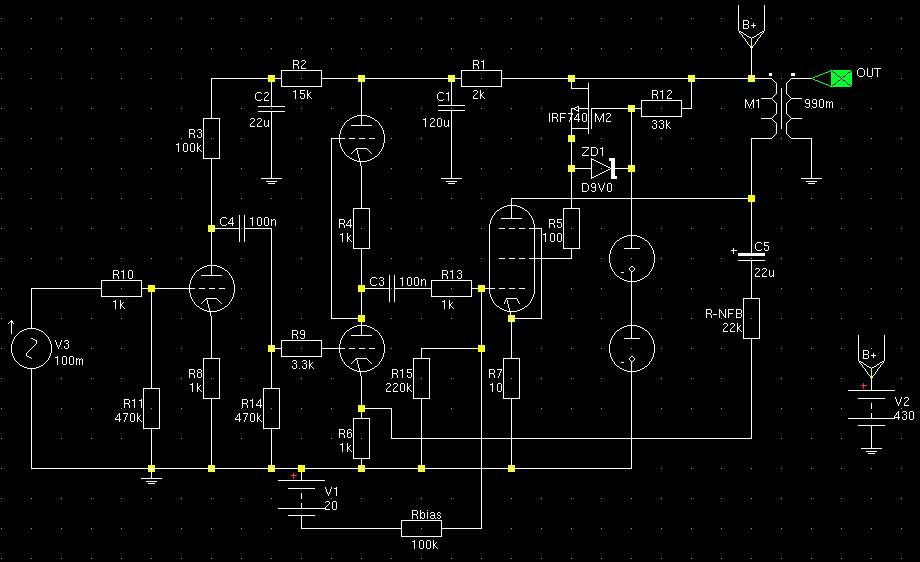
This is roughly what I ended up with before I had to mothball it:
The SRPP is now an SRPP+ and I can't recall what the feedback resistor ended up as. C5 could be eliminated with a couple of value tweaks, C3 is a worry if it goes into A2 and I need to add PSU cancelling feedback - it was my pseudo breadboard. When (eventually) the building is done I might start on a fresh chassis and order in some decent OPTs. I'll probably stick with the GU50's though as I like them and they cost peanuts. I'd like a little more DC coupling in there too if that can be worked in with an extra power rail in a bigger box.
As I left it with the VR tubes setting the screen voltage:
I modeled a little ECL82 amplifier a while back.
I attempted to apply plate to grid feedback but got some rather unspectacular results (triode driver so this shouldn't be such a surprise).
I then modeled plate to cathode feedback. The results were far more impressive with more clean power at lower distortion.
I built the amp using some salvaged console SE transformers with a bit of UL and the beast sounded far better than I ever expected it to. Feedback to the driver cathode rocks.
Shoog
Last edited:
Member
Joined 2009
Paid Member
Member
Joined 2009
Paid Member
Yes, I wanted as much feedback as possible and therefore as much gain as possible - so I chose pentode mode.
It's a bit silly really as triode is lower gain but has a little intrinsic feedback avoided by pentode mode - but pentode also generally gives you more power and I wanted that
I have not managed to audibly clip it on my 87dB/Watt speakers (Usher X718 IIRC). I generally listen to a mixture including AC/DC, Norah Jones, Katie Melua, Rainbow, Floyd, 'Stones, Sarah McLachlan, Deep Purple, Elephant etc. So I major on midrange tones for vocals, clear highs and a decent bass for drums and bass guitar.
The SRPP+ section allows a good voltage swing and was the only stage I tried that brought it to life - all other 'better' topologies (and yes - I did try!) sounded a bit lifeless and boring: I don't know why.
I always liked the sounds - my last amp was a class A SS (Usher R1.5) and I was always amazed how this little cheap SE managed to sound just as big and just as clean at high volumes. It also used less electricity
Source is obviously important and perhaps the first tube (no feedback) warmed the sound but it always sounded neutral.
I can thoroughly recommend the topology, I would however eliminate C5, think about how to stop C3 pumping up in class A2 (although I never noticed this) and add PSU noise/sag cancellation feedback in (ref JB @ tubelab). The PSU compensation is IMO an essential part of a decent amplifier and effectively removes the sonic signature of the PSU and it's dodgy electros etc etc. It also means you can use a nice simple PSU and make it perfect with a couple of cheap passives - it's a win-win.
add PSU noise/sag cancellation feedback in (ref JB @ tubelab).
You might have me confused with Broskie at Tubecad.
You might have me confused with Broskie at Tubecad.
Sorry! yes you are correct, the article was at tubecad - my memory's filing system is failing with old age.
Shoog: BTW I forgot to mention - thanks for posting up your experiences with driver+output tube loop.
It will be interesting to hear peoples experiences of moving the OPT out of the loop and adding feedback so that the primaries are driven correctly the first time - and letting the OPT do it's job of merely passing the music on.
It definitely made a huge improvement for me and it's also far more interesting than spending evenings battling motor-boating, ringing and trying to tame a method that has a large reactive element inside it.
Additionally negative feedback relies on the correction factor being amplified perfectly to work well - without distortion. This means that any feedback used to force the primary signal to be the correct shape is likely to work far better than any used in a GNFB loop to correct already distorted sound coming from the secondary. If that makes any sense
Of course we have to rely on the intrinsic distortion of the OPT a little more but we do in the speakers all the time, and some of them may have less linear materials in than the OPT. Except perhaps the Alnico ones, which IMO sound better than ceramics.
I think local feedback SEPs (LF-SEP?) are the middle ground that combine the best attributes of old fashioned PPs and the fully open loop SEs and more audio needs to benefit from this interesting layout. It also makes the best of available iron - a valuable thing indeed!
Isn't it difficult to connect multiple amps in one system...
I FIND IT DIFFICULT TO CONNECT MULTIPLE AMPLIFIERS WITHOUT CAUSING GND LOOPS.
Lets say the pre amp splits the outputs (signal & GND). The GND's finally meet again in the power distribution sockets. This creates a large "O" - Ring of a GND loop. Also important not to mess up a strict Left Right seperated GND in one of the amp as it often happens...In my expirience I lost my sweet ultra high resolution gained through many listening test when carefully fine tuning my amps when connecting another amp to it. Of course sometimes its just loud humm from the beginning ....
BUT IN GENERAL I AGREE TO THE IDEA THAT BELOW 70Hz OR SO ANOTHER AMP FOR E.G. A P-P DOES THE JOB = THATS LOGICAL.
Jochen
"If you are into multiple driver systems, build an amp for each driver and use an active crossover. Use SE for the highs, and maybe the midrange, P-P or SS for the woofer, and a 500+ watt class D amp for the thunderbox"
This suggestion is like putting a stiff drink in the hands of an Alcoholic!
I guess something I might strive toward for a reference 4way system..Hmm, couple of years maybe
I FIND IT DIFFICULT TO CONNECT MULTIPLE AMPLIFIERS WITHOUT CAUSING GND LOOPS.
Lets say the pre amp splits the outputs (signal & GND). The GND's finally meet again in the power distribution sockets. This creates a large "O" - Ring of a GND loop. Also important not to mess up a strict Left Right seperated GND in one of the amp as it often happens...In my expirience I lost my sweet ultra high resolution gained through many listening test when carefully fine tuning my amps when connecting another amp to it. Of course sometimes its just loud humm from the beginning
....BUT IN GENERAL I AGREE TO THE IDEA THAT BELOW 70Hz OR SO ANOTHER AMP FOR E.G. A P-P DOES THE JOB = THATS LOGICAL.
Jochen
Last edited:
T
SE does have its damping factor limitations, and requires a big expensive OPT, but that OPT can be operated in the sweet spot in its BH curve.
P-P can have solid state like damping factor but the OPT's magnetic domains must transition through zero magnetization and reverse direction often. This can mask low level detail in the music. Good OPT's can do a great job, but don't use more OPT than you need. Too much iron can cost you detail.
For the PP the effect of transition can be removed up to some 2-3W Pout for a 40-50 W amp by having an appropriate air-gap and small DC unbalance (very likely with real world tubes when best AC balance is achieved). That appropriate air-gap however will not compromise the higher power handling and inductance (that can still be about 3 times higher than the same SE transformer with appropriate air-gap).
So up to those 2-3 W output it is SE-like. For higher Pout the small air-gap will greatly reduce the residual magnetization anyway. If one wants to sort this problem out at all levels he can always go for some nickel alloys, nano-crystalline or amorphous that have very low coercivity (always using an appropriate air-gap, just smaller but good enough to cope with practical small DC unbalances) that wouldn't be so convenient for SE applications (although still usable).
The other day I was showing one example with the Lundahl LL1623 5.6K for a 40W EL34 UL 50% amp. If you ask for gap that produces 0.9T for 20 mA unbalance (this induction value is the "universal" reference for Lundahl as it is used for recommended max DC in their SE OT's) then at more practical unbalance of 4-5 mA the DC field will be about 0.2T and that means up to 1.5-2W Pout it won't go through zero. However inductance will be only reduced to about 120H (where the SE version for 60 mA DC has only got 46H) and power handling at 30Hz will be 50W (13W for the SE).
Last edited:
small DC unbalance (very likely with real world tubes when best AC balance is achieved).
"matched tubes" aren't! Most matched tubes are matched for idle current at a given bias voltage, and maybe similar Gm readings at one particular operating point. For truly perfect push pull balance they would have to have a matching set of curves AND the OPT would need perfect symmetry. These things are not going to happen....but IF they did, do you think the output tubes are going to age identically?
I find that the best real world operation occurs when you match the output tubes yourself under the conditions they will see, set the idle current balance for lowest distortion at low power level, and set the AC balance for lowest higher order distortion at the power level you will average in a normal listening session. The adjustments will interact so some tweaking is needed, and I am assuming that there are no crossover distortion issues.
Some budget P-P OPT's work best with a considerable DC offset, sometimes up to 5 mA, and some (Plitron toroidals) want a low offset. My 400 watt pair like about 2 mA in a 300 watt amp.
- Status
- This old topic is closed. If you want to reopen this topic, contact a moderator using the "Report Post" button.
- Home
- Amplifiers
- Tubes / Valves
- can SE bass be as good as PP ?