mpmarino said:One thing that I realise is that any discussion about mains in such an international forum can be complex and confusing due to the fact that there are so many systems out there. Apples and oranges as they say. When I said it is possible to short neutral to ground with no consequence in the US, I certainly did not mean for anyone to do it. I was just making the point that they are at the same potential. They SHOULD be bonded together right in your house at the panel. If they are not, you certainly have a wiring/grounding/safety issue.
Anyone unsure should get one of those plug in thingys
The last time I was in Benares (Varanasi) on the banks of the Ganges -- 1998 -- you could see the entire scene about 15 feet above your head was a birds nest of wires as the locals had tapped into the power and telephone lines. Systemization is out the window!
Earth...
Don't be under the impression that the LOCALS have tapped. The nest is a gift of the two departments 1.electricity and 2.telecom
India is as diverse in everything and everywhere.
But as for the safety earth...
The neutral and earth are never tied together anywhere. Individual electricity consumer will have a earth pit with 8 feet long pipe with holes. The pit is filled with layers of charcoal and salt, surrounding the pipe and this pipe is to be watered periodically for better results.
I can never think of zero volts at the neutral with the tranformer so far off, where the neutral is earthed(connected to mother earth)
15 feet above your head was a birds nest of wires as the locals had tapped into the power and telephone lines.
Don't be under the impression that the LOCALS have tapped. The nest is a gift of the two departments 1.electricity and 2.telecom
India is as diverse in everything and everywhere.
But as for the safety earth...
The neutral and earth are never tied together anywhere. Individual electricity consumer will have a earth pit with 8 feet long pipe with holes. The pit is filled with layers of charcoal and salt, surrounding the pipe and this pipe is to be watered periodically for better results.
I can never think of zero volts at the neutral with the tranformer so far off, where the neutral is earthed(connected to mother earth)
I loved the train ride from Benares to Bhubaneshwar !
here's a picture of the a.c. power through a good filament transformer -- nice harmonics.
here's a picture of the a.c. power through a good filament transformer -- nice harmonics.
An externally hosted image should be here but it was not working when we last tested it.
An active twin-T is much better. See, for example, http://www.analogzone.com/avt08062.pdf for some design guidelines. You'll have to attenuate the line voltage to accomodate an opamp, but you could conceivably implement the circuit with some discrete HV parts. Personally, I'd just attenuate, extract the residue, then amplify it. Opamps are your friend.
Could you elaborate?
-How to attenuate the line voltage to accommodate an opamp.
-How extract the residue
-How ampliify
Hi there and Happy New Year to all of you!
Old thread, I know, but I think it's very interesting to find out how noisy your power lines are.")
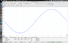
I've used my PicoScope 2204A to measure how my home AC lines look like. Because scope inputs are not isolated (cheap scope, I know, but it helps me a lot) the scope was inserted into the USB port of my laptop running on internal battery; this way I'm sure I won't burn anything, because scope and laptop are isolated from mains now.
I've also used a 230V to 120V transformer, because max. input voltage for this scope should not exceed 20V and by using a 10X probe that translates into a max. of just 200V.
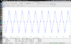
1st pic shows the mains AC sine-wave (not perfectly sine, but still looking good I's say).
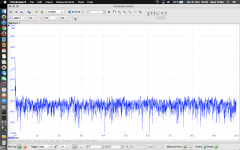
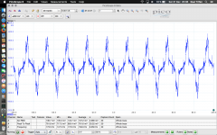
2nd pic shows AC noise up to 10MHz.
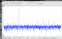
3rd pic shows AC noise up to 190Hz.
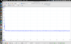
4th pic shows "average" AC noise up to 10MHz.
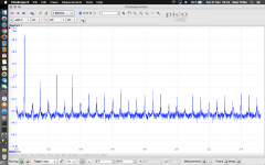
6th pic shows AC harmonics up to 1.5KHz.
The last 2 pics are showing the noise measured between GND and Neutral: 1st pic without anything connected to that circuit (136.7 mV RMS AC noise) and 2nd pic after connecting a vacuum cleaner (875.2 mV RMS AC noise). Looks like ground pollution by electronic appliances from our homes are indeed much trouble to our audio chain.
I've tried to lower the ground noise by using noise suppression filters, but of course I couldn't. The only way to lower the GND noise was to lift the ground correctly, not just lifting the GND pin (people might die because of this!), instead by using powerful diodes and caps between GND of the Hi-Fi equipment and the GND of the mains. This is similar with what Hum-X or other devices do and should be quite safe if using properly.
Note: While measuring the noise between Ground/Earth and Neutral I've swapped Neutral with Live and 230V got into my scope (I can't remember if I was using the 1X or the 10X probe). I'm happy that scope didn't broke and nor my MacBook Pro, so don't try using your scope probes directly into mains unless scope was designed for this task!
Old thread, I know, but I think it's very interesting to find out how noisy your power lines are.
I've used my PicoScope 2204A to measure how my home AC lines look like. Because scope inputs are not isolated (cheap scope, I know, but it helps me a lot) the scope was inserted into the USB port of my laptop running on internal battery; this way I'm sure I won't burn anything, because scope and laptop are isolated from mains now.
I've also used a 230V to 120V transformer, because max. input voltage for this scope should not exceed 20V and by using a 10X probe that translates into a max. of just 200V.
1st pic shows the mains AC sine-wave (not perfectly sine, but still looking good I's say).
2nd pic shows AC noise up to 10MHz.
3rd pic shows AC noise up to 190Hz.
4th pic shows "average" AC noise up to 10MHz.
6th pic shows AC harmonics up to 1.5KHz.
The last 2 pics are showing the noise measured between GND and Neutral: 1st pic without anything connected to that circuit (136.7 mV RMS AC noise) and 2nd pic after connecting a vacuum cleaner (875.2 mV RMS AC noise). Looks like ground pollution by electronic appliances from our homes are indeed much trouble to our audio chain.
I've tried to lower the ground noise by using noise suppression filters, but of course I couldn't. The only way to lower the GND noise was to lift the ground correctly, not just lifting the GND pin (people might die because of this!), instead by using powerful diodes and caps between GND of the Hi-Fi equipment and the GND of the mains. This is similar with what Hum-X or other devices do and should be quite safe if using properly.
Note: While measuring the noise between Ground/Earth and Neutral I've swapped Neutral with Live and 230V got into my scope (I can't remember if I was using the 1X or the 10X probe). I'm happy that scope didn't broke and nor my MacBook Pro, so don't try using your scope probes directly into mains unless scope was designed for this task!
Attachments
-
 Power_outlet_01.png641 KB · Views: 86
 -
 Power_outlet_02.png778 KB · Views: 93
 -
 Power_outlet_03.png807.5 KB · Views: 83
 -
 Power_outlet_04.png619.1 KB · Views: 78
 -
 Power_outlet_06.png685.1 KB · Views: 77
 -
 Ground_to_Neutral_noise_plain.png777.4 KB · Views: 57
 -
 Ground_to_Neutral_noise_vacuum_max.png703.7 KB · Views: 65
Interesting.
I use a small transformer in front of an audio interface to judge mains quality. It's something like 2,6 V output and it doesn't affect the frequency range I want to see too much. And that range is 0-100 kHz roughly. If there is suspicion of HF interference, I simply use SDR (software defined radio), with a 25 € USB TV receiver that convers most bands. Something like 100 kHz to 2 GHz.
Beats carrying around an old fashioned oscilloscope and I need the interface to measure acoustics anyway.
Once you can identify the frequency, it makes finding the source somewhat less of a riddle. Sometimes there's so much junk the frequencies don't matter. In that case, you can hear the noise without looking at a picture of it.
Sometimes frequencies like 1 MHz or even higher might affect internal opamp (or discrete circuitry) operation, especially if local decoupling is not perfectly done and if audio equipment is using high speed opamps. Imagine an input stage missing a low-pass filter on inputs and not having a correct local decoupling too, I really thing might start oscillating if 1 MHz might get injected into signal path from bad/cheap interconnects; into audio field this means more detailed and bright sound sometimes.
It's not that noises coming out from mains could actually get injected into the final audio sound through the power source (kind of small probability, especially with today power regulators and opamps having good noise & ripple rejection factor, high CMRR/PSRR), but more related to interconnect cables that are actually acting like small antennas and could gather mains noise and inject it into audio equipment. This happened to me several times when my XLR cables between DAC and headphone amplifier were nearby/on top of my computer desktop's power source: I got hum (probably from polluted mains ground coming from computer's metallic case) and a bit of hiss on my headphones. To resolve this issue I re-routed the cables few inches away from computer's PSU...nothing else.
Douglas Self in his book Audio Engineering Explained explained this phenomenon:
“[...] at higher frequencies, system wiring can become electrically long and transmission line effects, such as standing waves and resonances, become the dominant problem. For example, because a 25 ft (7.5 m) audio cable is a quarter wavelength long at 10 MHz, it becomes an antenna. At frequencies of 100 MHz or higher, even a 12 in (30 cm) wire can no longer be considered low impedance path.”
If you need to measure voltage, noise or harmonics on mains you may use the ouput transformer of a tube amplifier ( push pull plate winding on mains & voice coil to your scope ) to lower voltage & insulate your oscilloscope ... most of these transformer have a voltage ratio around 25 and will stand 240 volts at plate winding. Frequency response is of course audio spectrum.
If you want to look at powerline noise this is probably the best interface http://pdf.textfiles.com/manuals/STARINMANUALS/ETA/Archive/PowerProbe.pdf And then you need a scope with a very deep memory to see the transients and glitches.
Powerline noise goes past 30 MHz and there are more devices using power line communications than ever in the past so expect junk on the line. You really want a spectrum analyzer good for 50 MHz.
Powerline noise goes past 30 MHz and there are more devices using power line communications than ever in the past so expect junk on the line. You really want a spectrum analyzer good for 50 MHz.
Hi Walter,
Kinda expensive and for me still won't work because 2204A has a max. input voltage of 20V (or 200V with a 10X probe). So, this is why I'm using a 230 VAC -120 VAC transformer. I've used it to measure my 230V power lines and also to measure my Liebert/Emerson GTX3 3KVA UPS as well.
Kinda expensive and for me still won't work because 2204A has a max. input voltage of 20V (or 200V with a 10X probe). So, this is why I'm using a 230 VAC -120 VAC transformer. I've used it to measure my 230V power lines and also to measure my Liebert/Emerson GTX3 3KVA UPS as well.
- Status
- This old topic is closed. If you want to reopen this topic, contact a moderator using the "Report Post" button.
- Home
- Design & Build
- Equipment & Tools
- Can I use a scope to measure powerline noise?