


Do you prefer a tea?
Well Greg....do not like to move isnt?
You guys, if you want, go ahead with the thread, as many guys may be interested.
Despite i give up to put my hands on those things, i can change my mind, and also i am interested to learn more.
I am always changing my mind....and thanks God for that, as new inputs are giving me a more wide vision...it is wonderfull to change our minds...awfull is to be always the same.
So, the thread can go on, just feed it with ideas, links and comments.
regards,
Carlos
Carlos:
Anybody playing around with these PSUs has to be very careful as there is a part of the circuit that is mains-live and shows voltages high enough to cause serious injury. I posted schematics and asked you to study them and compare them with the real PSU, so that you could identify the live components and avoid touching them. I also have mentioned several times that a mains-isolation transformer is a *must* for off-line SMPS experimentation, because it reduces the chances of getting shocked and allows to connect the oscilloscope and other measuring equipment to the (now isolated) mains side. Furthermore, in some units one of the heatsinks is live, but a quick look at the PCB reveals this and other facts very quickly (that's why it's so important to study the circuit first).
I'm sorry for what happened to you.
Yes Eva, i remember you told me this.... was a foolish.
Well, this shows me how we can forget basic things when we geta little old.
I know that had live points there, but sometimes we forget those things...in special when we go to check overheated points and the small finger touch another point as an accident.
I am not hurt, just i learn to respect mains.... 220 Volts mains, and in special when it is feeding an oscilator, that is switching that "mains voltage" at high frequencies.
I think i am very lucky to be here, today.
And happy, as now i think i am very "charged"
regards,
Carlos
Check this link:
http://myweb.tiscali.co.uk/nuukspot/decdun/gainclonesmps.html
four SMPS to give + - 24V
Regards
http://myweb.tiscali.co.uk/nuukspot/decdun/gainclonesmps.html
four SMPS to give + - 24V
Regards
I think it will be enough....i am afraid is that some spurius signal enter to
saturate some component, or, at least, drive some components changing it's operational biasing point.
Afraid of some noises that we cannot listen, but may enter and produce some beat of frequencies.
I am too much ignorant to have sure about those things, but i think some residual noise will be presented.
As we cannot use a enormous bulk of condensers in the output, i feel afraid that this noise enter the amplifier.
Those things.....only those great EE we have can answer, if tune filtering will be enougth or if we will need to construct some tuned trap.
regards,
Carlos
Hi Carlos,
I just tell my story, as a simple man like you.
I have been several times for modification with SMPS PSU. All PSU are fine. Follow what I did :
1. Buy new PSU ATX!
2.Remove the transformer.
3. Soak the transformer with thinner for about 5 hours.
4. Dismantle, the cores, and windings. Write on paper for windings turns, directions, pins, do not forget everything you do. Leave the primary windings. Some PSU have half primary winding at outer and the other hals at inner. It may you remove a hal too.
5. Now rewind the secondary winding with small wire. You may need the power for control PSU inside and fane, 2 amps with small wire is enough. (Hey.. just small wire ok! see the book for 2 amps!) This trick is used to give more turn space for you new winding for your power amp. You know.... I know you smile! Make new turn with small wire for same number turn and direction and pins as existing.
6. Now, make new winding for full bridge, with as big as possible for the available space with number of turn refer to your existing 12V secondary winding to get voltage output. You know what I mean?
8. Reasseble the transformer, tapes, core. Use varnish or power glue to fix again.
7. Add Ultrafast Rectifiers (general diode will not work), and filters from old PSU output filter and caps. Use just small caps. If you want to use big caps, use delay relay contact and resistor in parallel, not direct connection, that cause PSU failed to started, by short circuit sense. All at full bridge arrangement. It may use a small PCB near the PSU ATX.
OK that is my trick, cheap and dirty. Ofcourse it is not EVA's class. But at least you will have 200W, even more is you lucky. Still short circuit protection, still have existing voltage, separate with control supply. The important things is the tricky have been succesfully done for powering my amp up to 200W.
I never did test with scope or others execpt the voltage and load. The tricky is not need knowledge of switching. The only need is calculate output refer to 12V winding, and remember the existing winding number and turns.
Good luck!
Kartino
Oh!...very good Kartino, clear and practical work...rewinding the trafo, and this i
Know how to do very well, as i use to make my own trafos.
I understood everything deeply.... was very simple and clear the explanation, and match my personal practical experience...my use to put the hands on work to construct transformer.
I will avoid the thinner only, as sometimes it attacks some plastic parts, but will do following your instructions.
Also i will try to find where is he feedback that may control the short circuit sensor to reduce its sensitivity...as i want a little bigger condensers, because of fear related residual oscilating frequencies.
I have bigger diodes to input rectifier (high voltage units, adequated ones, extracted from a 700 supply alike those ones)and bigger transistors adequated to 500 watts supplies....i am thinking to increase heatsink sizes and to produce a future (not now, as i will travel to our Capital, Brasilia and i will be there for some monthes) modified supply.
Also i am thinking to install a second fan, this one to exaust air....one pumping and other exausting.
Yeah...thin wires to have room enougth to install more turns...more voltage and less capacity of current.. 1 have many sizes near half milimeter and up to 2 milimeters, various gauges.
I will use 47uF-250 volts at the output to measure first the voltage obtained, even if the windings ratio informed me some expectation of resultant voltage....then i will increase till the threshold of the protection enter..... them i will reduce them, if not discovered how to delay the protection ....if a resistor, capacitor will delay....if you know, tell me weres to delay the protection.
Perfect explanation...easy to follow, understood completelly!, your message was complete to put my hands on.
My problem still my need to big condensers in the output...i am burning my mind in some way to block that surge current sensor, or to delay it's action till condensers is charged..... after beeing charge...ahahahahahahaha!...the current sensor can enter in operation...ahahahaha!
Many thanks by your kind cooperation...perfect!....you are envited to open your mouth (or to wrote) more often and about other things, as you explain things clear Mr Professor....Mr. teacher.
Congratulations!....very good work!
There are many good guys in our forum...hundreds, but their language is complicated to me, even English is complicated... and when the story is that the counterphase or the crossed point edge of the delay ballanced in the sinusoidal generator that is feedbacked with half impedance and 170 degrees phase displacement ..well...things turns hard to understand...you are simple, clear, and direct to the point...move your fingers and make turns!...yeah!....direct!...thank you!
Eva is also very clear...i have leaned a lot from her
I was invited for a investigation into the Federal Government, i will be busy for some monthes, related to put my hands on those jobs, of course i will have computers...many of them.
regards,
Carlos
Attachments

Hi Carlos,
You so exited! Did my explanation really meet your expectation?
But don't afraid when you test your modified PSU at first time and the PSU did not started. It the only possibility caused by short circuit protection, that triggered by rush current. It may caused by your diode that fast enough. It may caused by big charging capacitor. or your output shorted. Don't think complex such as your your control circuit failed since the PSU was works before modified.
For delay caps it is just simple delay. See attachment. Use simple delay relay will work. Another trick is you can connect the relay coil parallel to the DC protection relay coil that usually also have delay to avoid 'dug' at switched on if you have it. Remember that you still have 12V existing voltage to do this job, ok!
Oh yes... almost forget, remove the ceramic cap at the mains input to ground, unless otherwise your amp chassis is always grounded.
You can not increase the power max. because your PSU size transformer usually as ETD34 that arround 400W capacity. Hence the existing part is no need to modified. I have idea to try with bigger transformer and fets with small modification for current sensor. But I have no time yet. If you have time to try, it will be good to heard for other DIYer. It may you will the first people.
I have did also for Siemens SITOP 5, 24VDC from single output to +/- output. Of course we talk about DIY quality. But I think the quality is not so cheap and dirty. From my experience that PSu are better compared with conventional transformer, such as fast conversion, no grid hum, wide range voltage and less weight.
BTW Are we talk about PSU at SS amp forum?
Best regards,
Kartino
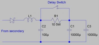
If you are worried about your huge caps activating the short circuit protection on the output, use a wirewound resistor in series with output to start, then clamp with a relay after a second or so.
In my experiences I've noticed even as low as 0.1 ohm will work fine, and that's low enough to not really need a relay, but you can still use one.
That circuit posted above is a perfect example. Of course, you can change the resistor, or delay to your preference.
Have fun, and post results when you get it working!
- Status
- This old topic is closed. If you want to reopen this topic, contact a moderator using the "Report Post" button.
- Home
- Amplifiers
- Solid State
- Can i use a computer power supply to power audio amplifiers?