Curiousity got the better of me, so last night I unwound the transformer to see if I could find the problem.
The secondary windings were fine, as were the insulation layers between them, and between the secondary windings and the primary.
The thermal fuse is also intact and had not blown. All connections were fine.
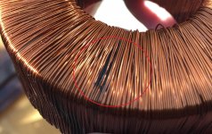
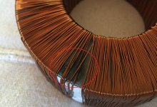
I noticed a slight discolouration on the primary winding when I looked very closely. Unwinding a layer showed the problem more clearly, as per the attached picture.
It looks like the coating on the wire has broken down, causing a short circuit which has melted the wire. It looks like this caused increased current draw, blowing the fuse each time I was testing. When I hooked it up to the bulb tester, it finally had a sustained current for long enough to melt the wire entirely, at which point it went open-circuit.
The secondary windings were fine, as were the insulation layers between them, and between the secondary windings and the primary.
The thermal fuse is also intact and had not blown. All connections were fine.
I noticed a slight discolouration on the primary winding when I looked very closely. Unwinding a layer showed the problem more clearly, as per the attached picture.
It looks like the coating on the wire has broken down, causing a short circuit which has melted the wire. It looks like this caused increased current draw, blowing the fuse each time I was testing. When I hooked it up to the bulb tester, it finally had a sustained current for long enough to melt the wire entirely, at which point it went open-circuit.
Attachments
The weirdest thing is that I used this amp more or less daily for the best part of a decade. Then it was out of action for a few years, then failed when I brought it out of retirement.
I would expect a manufacturing defect to show up a lot sooner.
I wouldn't think that a fault like that would cause any damage to anything else, or be caused by anything else. Do you think there might be other damage caused by this?
I would expect a manufacturing defect to show up a lot sooner.
I wouldn't think that a fault like that would cause any damage to anything else, or be caused by anything else. Do you think there might be other damage caused by this?
Looks like the tension control went wrong during winding that few turns and the wire was stretched. The operator should have discarded that winding and started over after correcting the problem with the machine, but he/she perhaps knew it would have a good chance to last a good part of a decade so why bother.
Replacement transformer has finally arrived. I'd appreciate it if someone could verify I've read the label correctly though; I don't want to wire it up out of phase...
The label on the transformer reads:
Primary: 0-115V, 0-115V (BLU. GRY. PUL. BRN.)
Secondary: 0-30V (ORG. YEL.)
0-30V (BLK. RED)
(N.B. that the replacement is a dual-primary, whereas the original was a single-primary)
Based on my reading of it, I should:
- Wire GRY and PUL together, insulate and secure them somewhere safely (to join the two primary windings in series)
- Wire YEL and BLK to the GND rail of the supply
Then BLU and BRN form the primary. ORG and RED connect up to the two 4A fuses
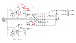
Or, using the original colour scheme from the schematic:
OLD -> NEW
YEL -> ORG
RED -> YEL
GREY -> BLK
PUR -> RED
ORANGE -> BLU
BROWN -> BRN
(with the new GRY and PUL wires joined, insulated and secured)
The label on the transformer reads:
Primary: 0-115V, 0-115V (BLU. GRY. PUL. BRN.)
Secondary: 0-30V (ORG. YEL.)
0-30V (BLK. RED)
(N.B. that the replacement is a dual-primary, whereas the original was a single-primary)
Based on my reading of it, I should:
- Wire GRY and PUL together, insulate and secure them somewhere safely (to join the two primary windings in series)
- Wire YEL and BLK to the GND rail of the supply
Then BLU and BRN form the primary. ORG and RED connect up to the two 4A fuses
Or, using the original colour scheme from the schematic:
OLD -> NEW
YEL -> ORG
RED -> YEL
GREY -> BLK
PUR -> RED
ORANGE -> BLU
BROWN -> BRN
(with the new GRY and PUL wires joined, insulated and secured)
Don't switch it on.
I read that as mains across BLU and BRN with GRY and PUL joined.
For the secondary I read as YEL and BLK joined which becomes the centre tap and ORG and RED become the two 30 vac outputs which are essentially the same as each other.
Be sure (edit... for next time)... wire a bulb tester to it and measure the secondary's from the joined centre tap. Then measure from 30vac output to 30vac output. You should see 60 volts. If you see only a volt or so then reverse one secondary winding.
Now I'm afraid I might be the bearer of bad news... I'm guessing you've bought this 30-0-30 tranny thinking it would be OK for the -/+28 volt rails in the amp (that's what I see in the manual I have).
A 30 volt tranny is going to give around -/+45 volts DC off load which is way way to high. The DC rails are 1.414 times the AC input which means you need an 18-0-18 tranny which would give around -/+25 volts DC at full current draw and around -/+28 lightly loaded. The transformer voltage is always quoted as an RMS figure. The peak voltage is 1.414 time that value, and that's what the PSU caps charge too. That RMS voltage is also quoted at max current delivery which means at light loads you multiply the voltage by the 'percentage regulation figure' given in the data sheet which will typically be perhaps 3 or 4 % for largish tranny.
I read that as mains across BLU and BRN with GRY and PUL joined.
For the secondary I read as YEL and BLK joined which becomes the centre tap and ORG and RED become the two 30 vac outputs which are essentially the same as each other.
Be sure (edit... for next time)... wire a bulb tester to it and measure the secondary's from the joined centre tap. Then measure from 30vac output to 30vac output. You should see 60 volts. If you see only a volt or so then reverse one secondary winding.
Thanks for confirming that.
Thanks for confirming that.
Hmmm, your welcome
") I guess not for the other news though !
I guess not for the other news though !Now I'm afraid I might be the bearer of bad news... I'm guessing you've bought this 30-0-30 tranny thinking it would be OK for the -/+28 volt rails in the amp (that's what I see in the manual I have).
A 30 volt tranny is going to give around -/+45 volts DC off load which is way way to high. The DC rails are 1.414 times the AC input which means you need an 18-0-18 tranny which would give around -/+25 volts DC at full current draw and around -/+28 lightly loaded. The transformer voltage is always quoted as an RMS figure. The peak voltage is 1.414 time that value, and that's what the PSU caps charge too. That RMS voltage is also quoted at max current delivery which means at light loads you multiply the voltage by the 'percentage regulation figure' given in the data sheet which will typically be perhaps 3 or 4 % for largish tranny.
I was going off the parts list which I have as part of the schematic. There, the transformer is listed as:
230V 120VA 30VAC x2 Toroid transformer.
Is that not correct?
Thanks Mike, although it seems clear cut to me. The TDA1514 chips have an absolute max rating of -/+30 volts dc and so that puts a limit of 18-0-18 Vac on the tranny.
We never even talked about possible voltages for a replacement.
Yeh, I assumed that I knew what I needed, based on the parts list. I guess that was a poor assumption.
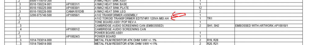
Looks like we have the same one, but I think you're looking at the "SUBTRACTIONS" section of the Bill of Materials, whereas I was reading the "ADDITIONS" section
I was looking at line #15 of page 2, which lists "230V 120VA 30VACx2 Toroid Transformer"
Perhaps that was my error. I hadn't noticed that this was a addition/subtraction list rather than a regular parts list. (or even that there was a second listing further down)
I guess I need to go order another transformer.
Thank you for pointing out my error, you at least saved me from frying the rest of the amp by putting in the wrong transformer...
Plus I wasn't aware of how to calculate the DC output voltage from the transformer rating, so I've also learned something...
Last edited:
- Status
- This old topic is closed. If you want to reopen this topic, contact a moderator using the "Report Post" button.
- Home
- Amplifiers
- Solid State
- Cambridge Audio A1mk3SE repair