I have a small transformer for the timer circuit.Ah... but how to power it?
I took a 50ohm 50W large resistor in an Aluminum case. You can line up say 5pcs 10ohm 10w cheap ceramic wire resistors. https://www.ebay.com/itm/22585407833210 ohm 50W resistor seems about right for a 230V 2A circuit
Last edited:
I believe you, that's your occupation. A few months ago I replaced a small EI Chinese transformer in the Microlab 2+1 PC speakers. The primary winding partially melted the plastic, and then the thermal fuse cut the current. I put a twice as strong torus transformer. Most of those factory transformers in commercial devices are undersized, they heat up a lot and die over time. For my DIY devices, there is no saving on the transformer.You work at hobby level, too small a sample to be statistically significant.
As a repair guy, I have replaced over 100 PTs, in any level of damage, from partially molten plastic bobbins to toasted paper tape to burnt wire insulation to copper molten to a blob.
Other Techs here can testify to similar horror stories.

Last edited:
just try to understand how just a main fuse calculated for the whole transformer can still protect a single secondary effectively
How about install a thermal fuse in series with the primary winding so that if any winding in the transformer overheats, the thermal fuse will blow and protect anything downstream. I guess that's why many manufacturer do not fuse the secondary windings.it will be a toroidal, a custom toroidy audio grade one
There are also time delay relays that can be used on mains voltage without the need for an additional power supply.so i guess i could inrush current limited the transformer and use 5V from a secondary to power on the relay,
https://www.mouser.com/c/electromec...-relays-accessories/time-delay-timing-relays/
Last edited:
500F supercap is nonsense! Even if you use inrush current limiting protection during start up. What do you thinck will happen the moment the mainvoltage jumps up because some other heavy load on the grid gets switched off ?
There is no fuse rating that could deal with such a situation and at the same time protect the way a fuse is supposed to protect.
There is no fuse rating that could deal with such a situation and at the same time protect the way a fuse is supposed to protect.
Last edited:
im not sure if this works, this would just work if one secondary on my 8 secondarys example can still handle the current to fully saturate the primary, i dont think they are but i could be wrongHow about install a thermal fuse in series with the primary winding so that if any winding in the transformer overheats, the thermal fuse will blow and protect anything downstream. I guess that's why many manufacturer do not fuse the secondary windings.
ah yes i saw some of them, specially the din rail ones, but i wanna avoid getting a cheap SMPS into the device... thats why i kinda like the "power the relay from behind the transformer" approachThere are also time delay relays that can be used on mains voltage without the need for an additional power supply.
i might test either powering directly from secondary without any delay and see if this works or use possibly a microcontroller to delay it further 2-3 seconds
well because you say it like that the voltage jumps up and all caps create a heavy inrush current but im unsure how important this is in practical sense, our grid here in germany is always above 230V (and i never saw it over 240)500F supercap is nonsense! Even if you use inrush current limiting protection during start up. What do you thinck will happen the moment the mainvoltage jumps up because some other heavy load on the grid gets switched off ?
i hope that these current limiting power switch ic will work tho regarding evening out the charge current etc..
i could also use smaller caps, im still kinda unsure, a supercapacitor "battery" power supply off the grid, just connecting to the grid for charging also sounds fun
Fusing is quite difficult to get right, especially if you try to turn it into an exact science. You want the fuse to protect the wiring in your house in case something goes wrong. So you want the lowest ampacity possible. On the other hand, you really don't want the fuse to blow during normal use, which pushes the ampacity of the fuse up.
The inrush current is the main challenge for the fuse. Even a small toroidal power transformer can draw hundreds of ampere of inrush current. I measured quite a few such toroids in my Ultimate Guide to Soft Start Design.
If you want to avoid nuisance blows, rating the fuse for 2-3 times VA/Vmains is a good starting point. If the fuse ampacity starts getting ridiculous (say approaching 10 A) you really ought to consider using a soft start circuit. Alternatively, I suggest studying Littelfuse's guide on the topic: https://www.mouser.com/catalog/supplier/library/LittelFuseElectProductCat.pdf
I would not bother with secondary fuses. I always use fuses on the primary of the transformer. That's made easy by using an IEC inlet with a built-in fuse holder.
Any circuit attached to the secondary of the transformer will do nothing to prevent the inrush of the transformer itself, so you need to deal with that either way.
Tom
I think there is a reason some manufacturers use Bussmann MDQ series dual-element, time-delay fuse.
"These cartridge-style, time-delay glass fuses tolerate temporary inrush currents without opening, which prevents nuisance-blowing from equipment startups, they open to disconnect an electrical circuit when exposed to sustained loads and short circuits."
"These cartridge-style, time-delay glass fuses tolerate temporary inrush currents without opening, which prevents nuisance-blowing from equipment startups, they open to disconnect an electrical circuit when exposed to sustained loads and short circuits."
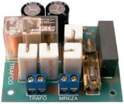
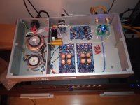
A few that I know use this circuit. The retention time is about 2s. You can extend that time if you put larger electrolytes than 2x470uF, say 2x1000uF or 2x1500uF. I would also add another 10ohm resistor, to make them 5x10ohm and reduce the starting current a little more. One company that makes transformers in our country also sells this type of assembly. I don't really like that little relay there and thin leads on the PCB . A resistor should be added to the line with the relay coil in order to set the voltage on coil to be close to 24VDC.
https://electronics-diy.com/schematics/451/delay_circuit_for_toroids.htm
https://electronics-diy.com/schematics/451/delay_circuit_for_toroids.htm
Attachments
Last edited:
ah thank you! its so hard to find real life examples in electronics... and im having lately a bad time with google ... AI getting better and the damn google search is getting worse...A few that I know use this circuit. The retention time is about 2s. You can extend that time if you put larger electrolytes than 2x470uF, say 2x1000uF or 2x1500uF. I would also add another 10ohm resistor, to make them 5x10ohm and reduce the starting current a little more. One company that makes transformers in our country also sells this type of assembly. I don't really like that little relay there and thin leads on the PCB . A resistor should be added to the line with the relay coil in order to set the voltage on coil to be close to 24VDC.
https://electronics-diy.com/schematics/451/delay_circuit_for_toroids.htm
but that looks fairly simple to replicate i might just do this circuit with a higher quality relay and thicker traces and the PCB goes with the EMI filter in a small metal box since both have 230V on them...
i could also modify the circuit a bit so the relay gets hooked up with two wires (Lin and Lout) where Lin is externally fused (iec socket or fuse holder), and one path on the PCB trough the resistors and the other directly trough the relay which sits right at the screw terminal..
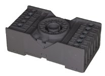
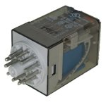
That assembly works but is not flexible. It is a very old circuit, it looks a bit like light timers in old buildings. The voltage on the coil relay can be significantly higher than 24VDC, so it is necessary to determine a series resistor by experiment. The time is not precise, it depends on those electrolytic capacitors. That's why I took a small transformer and a timer with which I can set the time. And the relay is like this (oktal socket, I had a few pieces of that ).
).Attachments
Last edited:
i will keep that in mind and add a footprint for a resistor and measure how much comes out and adjust the resistor, i guess these older relays had larger spec range? maybeThe voltage on the coil relay can be significantly higher than 24VDC, so it is necessary to determine a series resistor by experiment.
as long it gets me to a few seconds im fine with it... tho im kinda wondering how 2x470uF already provide 2s delay, i guess because of inrush current too and not stabalizing the rail yet.. but 2 seconds seems fairly much for 2x470uF, how much would 2x20000uF last? but i guess this also has todo with ESR right?The time is not precise, it depends on those electrolytic capacitors.
ah never saw these but i guess its industry style stuffAnd the relay is like this (oktal socket, I had a few pieces of that
3 seconds is enough, during that time the transient phenomenon is over. The voltage on the relay coil and time depends on the resistance of the coil, that's why I don't like that schematic. Put a bigger relay with lower coil resistance and the voltage will be too low. It can be adjusted with elements in front of the diode bridge, but I say it is not flexible at all.
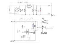
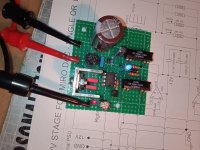
The real thing is a small print transformer 5VA /13-15VAC, 7812, NE555 and strong relay 12VDC.
The real thing is a small print transformer 5VA /13-15VAC, 7812, NE555 and strong relay 12VDC.
Yeah. Definitely use a slow-blow or time-delay fuse for mains fusing. But even the fancy fuses will require some oversizing to prevent nuisance blows.I think there is a reason some manufacturers use Bussmann MDQ series dual-element, time-delay fuse.
"These cartridge-style, time-delay glass fuses tolerate temporary inrush currents without opening, which prevents nuisance-blowing from equipment startups, they open to disconnect an electrical circuit when exposed to sustained loads and short circuits."
Tom
Maybe it's easiest to take a ready-made Chinese board where everything is already there.ah nice, thank you yea that would do the trick too, i might play around with a microcontroller to blink the power button led while the delay is running or something along the lines, i have to see what i can come up with
#32
- Home
- Design & Build
- Construction Tips
- Calculating Transformer Fuse