yldouright said:AudioFreak, Bob Ellis
Half of the Aleph-X amp is indifferent to the load, it just doesn't see it so even though the volts swing from both sides, the relevant number for calculation is the actual rail from either side NOT the whole swing on both sides.
ok so you're telling me that at max power output, you believe the amp will have 1/2 of the +ve rail on 1 output terminal and 1/2 of the -ve rail on the other terminal?
Let's see if I can help explain.
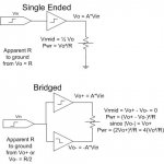
In a bridged system, we have two amps with the outputs connected, and one driven with the opposite phase. For the sake of simplicity, lets say that the amp has a gain of 1.
Ok, one volt is put into the inputs. Amp one is driven in phase, and the output swings to 1V. Amp two is driven out of phase, and the voltage on the output swings to -1V. This means the voltage between the two amps is 2V. There is no reference to earth at all.
Is that any clearer?
yldouright,
I might just add that you can not duplicate even a simple version of this circuit in PSUD2 and given your trouble understanding the basic functions of this circuit, I suggest you stop trying to use an invalid model. This might at least allow us to show you where your PSUD2 model differs from the basis of the Aleph-X circuit.
I might just add that you can not duplicate even a simple version of this circuit in PSUD2 and given your trouble understanding the basic functions of this circuit, I suggest you stop trying to use an invalid model. This might at least allow us to show you where your PSUD2 model differs from the basis of the Aleph-X circuit.
One side is swinging to the positive rail while the other is swinging negative. The load sees the differential voltage - twice the swing of either side. The current sources are not a voltage reference, the voltage at the "bottom" of the source swings with the signal.
There is a reason people say a bridged amplifier "sees" half the load. This refers to each section. Using Pinkmouse's example - one side at 1V, the other side at -1V, for 2V across the load. Let's say we have a 4 ohm load, the current will be .5 A. This current will be sourced by one side and sunk by the other.
What load would cause each side of the amp to deliver .5A at 1 volt? 2 ohms would - hence the reference to "seeing" half the actual load.
If you want to play with models, try simulating a son of Zen in something like circuitmaker to help you understand bridge mode operation.
yldouright,
While I would be the first to admit that there are a lot of confused people in the world, in this case BobEllis, AudioFreak, and pinkmouse are right.
As I see it, you have two alternatives:
1) Don't even think about building such a circuit until you figure out what it's all about.
--or--
2) Damn the torpedoes, full speed ahead...build one and watch it operate in order to gain fuller understanding.
I vote for option 2, but then I've always been glad to push on into new things. It's how I learn.
The one caveat, use a hand held meter or one that is completely isolated from ground to measure the output or you will only see half the output. Corollary, be sure that you measure across the load, not from one side to ground. There is no "ground" at the output of an amp like the Aleph-X.
Trust me on this one. A properly biased bridged amp has four times the power of the equivalent single-sided amp. With the same rail voltage, it will swing twice the output voltage, and in consequence the current is also higher.
Grey
GRollins said:... there are a lot of confused people in the world, ...
Unfortunately, I am always one of them.
Tonight, I have read through this thread with great interest, and at the end I am again confused.
Let me see in this way:
Aleph AX has two sides which are bridged by load resistor (speaker). From the center of the load resistor, both sides are super-symmetric. This means that I could assume the center of the load resistor as a virtual ground because the voltage is always zero with respect to the ground and no current flows to the ground.
I will stand on this virtual ground (center of the load resistor), where I can observe current flowing through the load resistor from one end through the point I am standing to the other end. Then, I will see the voltage of each end of the load resistor. It must be that each end has the same voltage, but of opposite polarities. If one end has +V (towards the +rail voltage), the other end will have -V (towards the -rail voltage), i.e. across the load the voltage must be 2V (towards 2 x rail voltage).
Now I need three eyes. One of my eyes watches current flowing through the load resistor and at the same time the other two eyes should watch the both ends whether +V and -V reach the max/min allowable values. As soon as the +V and -V reach to the max/min allowable values (or the current flow reaches to the maximum allowable value), I should shout, all freeze!!! And check the amount of the frozen current in the load resistor and, with it, calculate the load power.
I will repeat this with different load resistors.
My...... what I am talking about...???
I am pouring oil into further confusion...

Without trying to takes sides maybe some raw math will help.
As hands on do it ourselves kind of people, I think we should respect the drive to challenge and improve what many would consider gospel and untouchable... even if it's as simple as instructions.
Maybe an image will help push conversations back to a productive level.
--
Danny
As hands on do it ourselves kind of people, I think we should respect the drive to challenge and improve what many would consider gospel and untouchable... even if it's as simple as instructions.
Maybe an image will help push conversations back to a productive level.
--
Danny
Attachments
Would it help to think of the output as a see-saw, with the fulcrum being the virtual ground? As one side goes up, the other goes down. When one is maximum +, the other is maximum -. The absolute value of the difference in the "altitudes" of the ends of the see-saw is the voltage across the load. The current will behave accordingly.
Grey
Grey
yldouright,
I have not seen the spreadsheet but I'm basing my reply to previous posts (I have MS Works spreadsheet and cannot open Excel sheet)...
An 8A entry with four mosfets means 4A on each mosfet with two fets (CCS fet and output fet) on each side of the output circuits. This means about 0.125 ohm of source resistors with 0.5V of CCS reference voltage. 8A is the total bias but splits to 4A each half of the bal circuit.
Danny
Thanks. The diagram explains much better way.
")
Not to argue, but for me to understand better. The Aleph X is an amp doing control of the output current. And, injects current to load resistor. By doing so, the voltage appears across the load resistor. From load resistor's point of view, the current happens first, and then voltage will behave accordingly.
You are informing opposite way. Nevertheless, my understanding reasonable?
Thanks. The diagram explains much better way.
GRollins said:... the voltage across the load. The current will behave accordingly.
Not to argue, but for me to understand better. The Aleph X is an amp doing control of the output current. And, injects current to load resistor. By doing so, the voltage appears across the load resistor. From load resistor's point of view, the current happens first, and then voltage will behave accordingly.
You are informing opposite way. Nevertheless, my understanding reasonable?
yldouright,
To answer the question that appears in post 1 of this thread....
Please refer to the schematic I've attached below ... forgetting all the supporting circuit, this is the output stage of the AlephX. Each of the current sources contain 1 fet and as you can see, there are another 2 fets, 1 on each side of the circuit. The resistor in the middle of the circuit is the speaker.
Now assuming 8 amps total bias and 4 fets as per your example.......
At idle, 4 amps flows thru each of the 2 current source fets and down thru the output fets. So, I hope this help you to see that for 8 amps total bias, at idle each fet carries 4 amps and 1/2 of the rail to rail voltage (at idle both of the output terminals are ideally at 0 volts).
If we then consider the current gain = 0.5, during peaks each of the current sources can double their current and so they can each source or sink upto 8 amps. Now because each 1/2 of the circuit IS IN SERIES with the the other 1/2 of the circuit, the maximum current that can be delivered to the load equals the maximum current thru one side of the circuit or in this case 8 amps.
Attachments
AXE spreadsheet
I think the confusion is the statement in the spreadsheet.
One might asume that 8 amps total bias fot one channel with 4 FET's means 2 amp per FET.
Both the positive and the negative rail have to supply the 8 amps
Thus 2*railvoltage*bias=dissipation.
Perhaps it's clearer if the spreadsheet mentioned in cell D13 Total bias current per rail instead of per monoblock.
AudioFreak said:No, Aleph / Aleph X output a voltage proportional to the input voltage and current behaves accordingly.
The output voltages appears the same even if the speaker is disconnected? For me to learn more, how it works?
I'm not sure why you feel that it should be different.
Voltage can be present without current. An example of this is an open circuit such as a power outlet in the wall with nothing plugged in. The voltage (120, 240, whatever) is there regardless of whether any current is flowing. The voltage does not suddenly appear when something is plugged in--it's already there. Mathematically, the voltage sees an infinite load. By I=V/R, as R approaches infinity the current vanishes, yet the voltage is still there.
The same thing applies for an audio power amplifier.
Grey
Voltage is sometimes known as Potential Difference, or PD.
One way of making a mental model of this is to think of elevation instead of voltage. If you imagine a mountain, you can have a point that is say, 100m higher than another. Nothing will happen, and this state can last for thousands of years. If you put spill some water at the higher point however, it will flow downhill, and if you have enough, can be used to do work, like drive a watermill.
One way of making a mental model of this is to think of elevation instead of voltage. If you imagine a mountain, you can have a point that is say, 100m higher than another. Nothing will happen, and this state can last for thousands of years. If you put spill some water at the higher point however, it will flow downhill, and if you have enough, can be used to do work, like drive a watermill.
Hi Guys,
I would have thought that the problems would have been solved after my 3 internetless weeks ( very relaxing) of South Africa
As far as my (very subjective) opinion counts I can say that my Aleph-X behaves exactly as my spreadsheet predicted but maybe it only behaves this way cause I build it
William
- Status
- This old topic is closed. If you want to reopen this topic, contact a moderator using the "Report Post" button.
- Home
- Amplifiers
- Pass Labs
- Calculating the AlephX