Take a close look at the AC line voltage, and check to see what you may have plugged into any outlets common to the one the amplifier PSU is plugged into. Try loading the supply into just a large power resistor and see if the behavior persists - I suspect the cause is external to your amp.
About one year ago I asked my landlord if he could take care of one thing for me. I wanted a bunch of separately feeded (grounded) power outlets in my hobby room, connected to a real "earth fault breaker" (is that really the correct name?).
No problem! An electrician installed a new cable all the way from the main central and installed 8 outlets for me. So far no problem.
It seems though, that even a very small current causes a quite large voltage drop. The 3hz voltage drops I had were actually caused by my soldering station. These disappeared immediately when that was turned off.
Of course, all my other equipment in here causes a lot of voltage swings. Turning my lab power supply on caused a drop at about 6 volts. Even without any particular things happening I have a ripple at about 1vpp.
Connecting the tube amp PSU to another outlet somewhere else in my apartment gives me a ripple at about 200mvpp. Also, there are no large spikes everytime I start something.
The quest goes on. Maybe now I can focus on the actual project")
No problem! An electrician installed a new cable all the way from the main central and installed 8 outlets for me. So far no problem.
It seems though, that even a very small current causes a quite large voltage drop. The 3hz voltage drops I had were actually caused by my soldering station. These disappeared immediately when that was turned off.
Of course, all my other equipment in here causes a lot of voltage swings. Turning my lab power supply on caused a drop at about 6 volts. Even without any particular things happening I have a ripple at about 1vpp.
Connecting the tube amp PSU to another outlet somewhere else in my apartment gives me a ripple at about 200mvpp. Also, there are no large spikes everytime I start something.
The quest goes on. Maybe now I can focus on the actual project
The struggle continues...
I have fixed a couple of issues. Added grid stopper resistors to g1 of all tubes.
Adjusted the bias for all tubes. Turned out that the multimeter I used when adjusting the bias for the c3g tubes had very low impedance - which of course led to faulty readings. Used the oscilloscope instead and got better results.
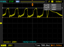
Anyway... The attached image shows some strange oscillations at the output (anode) of one of the tubes in the driver stage at about 1Hz. Strangely, this only happens for the tube which grid is connected to the inverting output of the PI.
The oscillations have very big amplitude. What you actually see at the bottom of each swing is the 2.5kHz signal I applied to the input. This 2,5kHz signal can also be heard from the tube itself.
Also, this only happens when the power tubes are in place.
I have fixed a couple of issues. Added grid stopper resistors to g1 of all tubes.
Adjusted the bias for all tubes. Turned out that the multimeter I used when adjusting the bias for the c3g tubes had very low impedance - which of course led to faulty readings. Used the oscilloscope instead and got better results.
Anyway... The attached image shows some strange oscillations at the output (anode) of one of the tubes in the driver stage at about 1Hz. Strangely, this only happens for the tube which grid is connected to the inverting output of the PI.
The oscillations have very big amplitude. What you actually see at the bottom of each swing is the 2.5kHz signal I applied to the input. This 2,5kHz signal can also be heard from the tube itself.
Also, this only happens when the power tubes are in place.
Attachments
Sorry about the monologue
Maybe the problem is feedback caused by the voltage drop in the inductor and the transformer.
This would cause the inverted output of the PI to swing - which makes the signal to the following driver tube very large. This would of course result in a very large signal to the power tube (KT88), leading to a large current swing - causing the voltage drop in the inductor...
Maybe I should use the separate 165VDC winding on the power transformer for the c3g power supply?!
Anyone have any experience with this? It can not in any way be unique?
Hi Nlinus,
That sounds quite plausible. Unintended feedback across the supply impedance is the classic cause of motorboating. Using separate windings, rectifiers and filters should definitely help, but you can also try reducing the AC coupling time constants between phase inverter and output stages.
Best regards,
Marcel
- Status
- This old topic is closed. If you want to reopen this topic, contact a moderator using the "Report Post" button.