hi all
i am getting lower current than stated on datasheet of c3g.
just wondering if i connected it correctly as a triode strapped pentode.
datasheet can be found here
as a triode strapped pentode,
i have connected Ua = U2 = anode voltage, U3 = 0v, U1 = grid, pin 5 and 7 to cathode.
is that right?
cheers
garbage
Garbage,
I've been posting in a lot of your threads... I assure you I'm not following you around
Pin 1: heater
Pin 2: g3 - tie to anode
Pin 3: anode
Pin 4: g2 - tie to anode
Pin 5: cathode
Pin 6: grid
Pin 7: cathode
Pin 8: heater
(valve pins are numbered clockwise with from the key/gap from bottom view)
What are the anode-cathode and g1-cathode voltages you are measuring, and the current? Sometimes valves deviate a little from spec.
C3g
Hi Garbage,
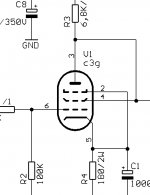
don't know whether I can be of much help, but since I am in the process of building a headphone amplifier using the C3g , I might as well post part of my original schematic. This is how the originator of the schematic, one Mr. Siemens, wired things up.
Good luck,
Oliver
i have connected Ua = U2 = anode voltage, U3 = 0v, U1 = grid, pin 5 and 7 to cathode
Hi Garbage,
don't know whether I can be of much help, but since I am in the process of building a headphone amplifier using the C3g , I might as well post part of my original schematic. This is how the originator of the schematic, one Mr. Siemens, wired things up.
Good luck,
Oliver
Attachments
Re: C3g
i realised, and i appreciate your replies, no worries mate.
i only measure the anode voltage and the drd choke with current passing thru it. the voltage is 182.3 and 7.36mA with 2.7v bias.
will follow your suggestion to measure the p-k voltage and g1-k voltage.
it's a great help. it is a triode strapped pentode right? i notice from another datasheet that pin2 is connected to pin 5/7 too.
audiousername said:
I've been posting in a lot of your threads... I assure you I'm not following you around
Pin 1: heater
Pin 2: g3 - tie to anode
Pin 3: anode
Pin 4: g2 - tie to anode
Pin 5: cathode
Pin 6: grid
Pin 7: cathode
Pin 8: heater
(valve pins are numbered clockwise with from the key/gap from bottom view)
What are the anode-cathode and g1-cathode voltages you are measuring, and the current? Sometimes valves deviate a little from spec.
i realised, and i appreciate your replies, no worries mate.
i only measure the anode voltage and the drd choke with current passing thru it. the voltage is 182.3 and 7.36mA with 2.7v bias.
will follow your suggestion to measure the p-k voltage and g1-k voltage.
Stixx said:
don't know whether I can be of much help, but since I am in the process of building a headphone amplifier using the C3g , I might as well post part of my original schematic. This is how the originator of the schematic, one Mr. Siemens, wired things up.
Good luck,
Oliver
it's a great help. it is a triode strapped pentode right? i notice from another datasheet that pin2 is connected to pin 5/7 too.
Hmmm...
A strange one ? Not really . I'd put this down to device variation which is a typical of high gm valves . If it's not a new one then there also may be the possibility the valve under test is a little on the weak side
cheers
316a
audiousername said:That's odd. From ~180Va-k and ~-3Vg1-k you would be expecting about 12mA of current, almost twice what you are getting!
This is a strange one....
Don't worry about measuring the voltages, what you told me is fine
A strange one ? Not really . I'd put this down to device variation which is a typical of high gm valves . If it's not a new one then there also may be the possibility the valve under test is a little on the weak side
cheers
316a
Re: Hmmm...
Of course what you're saying is correct. Although 17mA/V isn't super-high, device variation is always something to consider with high transconductance valves.
Garbage,
You could always just swap the valve drawing too little current with the other channel or a spare. I can't believe I hadn't said it before. It should have been the first thing I said!
316a said:A strange one ? Not really . I'd put this down to device variation which is a typical of high gm valves . If it's not a new one then there also may be the possibility the valve under test is a little on the weak side
Of course what you're saying is correct. Although 17mA/V isn't super-high, device variation is always something to consider with high transconductance valves.
Garbage,
You could always just swap the valve drawing too little current with the other channel or a spare. I can't believe I hadn't said it before. It should have been the first thing I said!
Re: Re: Hmmm...
right, i actually wanted to do that over the weekend. i have 4 in all to play around with.
but was pretty tied up with sanding the aluminium panels for the chassis.
i did solder pin 2 to cathode as Oliver suggested, that raised current to 8.15mA, but could be due to the batteries losing some charge. i measured across the batteries and they are 2.66v.
cheers
garbage
audiousername said:
Garbage,
You could always just swap the valve drawing too little current with the other channel or a spare. I can't believe I hadn't said it before. It should have been the first thing I said!
right, i actually wanted to do that over the weekend. i have 4 in all to play around with.
but was pretty tied up with sanding the aluminium panels for the chassis.
i did solder pin 2 to cathode as Oliver suggested, that raised current to 8.15mA, but could be due to the batteries losing some charge. i measured across the batteries and they are 2.66v.
cheers
garbage
- Status
- This old topic is closed. If you want to reopen this topic, contact a moderator using the "Report Post" button.
- Home
- Amplifiers
- Tubes / Valves
- c3g connections