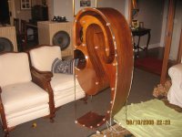
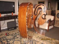
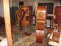
well,I knew they were yours. Since I saw them in red laquer and transparent sides the photo went straight to the folder "casse"(boxes)in my computer.
What about CAD and CNC? With those instruments many of my projects would take shape in the real world ! I'm talking about angles,volumes cut by secant planes,perfect alignment of all the parts without having issues etc.
What about CAD and CNC? With those instruments many of my projects would take shape in the real world ! I'm talking about angles,volumes cut by secant planes,perfect alignment of all the parts without having issues etc.
Badman, my CNC slicing technique means I can build a cabint easily on a weekend...so that argument is not entirely valid. Also, all of my designs can be bought by DIY enthusiasts, who wish to build something a little different, and can do so in hours, not weeks per normal manufacturing techniques. (Try building a Tannoy GRF in one weekend....!) If this means parallel walls, so be it.
The waste argument has some validity, but I nest the smaller section of the horn in he mouth of the larger piece...so waste is reduced considerably. But, I consider this waste to be perfectly acceptable in order to create such an exotic scultpure. The speaker is as much a talking piece as listening....especially in this new all-ply version.
On the non parallel walls, I guess I just have to leave your concerns to you. But please remember, I'm using a 2-dimensional cutting process, not a multi-axis router....so saying that I've just failed to complete the last part of the project properly is a little unfair. To build a horn as you've suggested would require a completely different approach. As I said earlier, I commend those folk who do such work.
I'm wondering what your view is of the Hedlund horn, or the large Big Fun Horn? Bother receive oustanding reviews the world over.....
I'm also reminded of the famous vintage speakers such as the JBL Paragon, Jensen Imperial, Tannoy GRF's etc (which I build - see attached). All of these designs incorporate 2 parallel walls..usually top and bottom. Are you also suggesting these world-renowned designs are flawed?
I trust the note in your signature isn't refelective of a general dislike for these types of horns. If it is, then the criticisms raised are really just from a personal bias, nothing more....!;-)
Kind regards.
Let's start with one important point- this is out of place here as you sell the things. They're not strictly DIY. As to you building one in a weekend, DIYers can't BUILD one in a weekend, they can ASSEMBLE one in a weekend. You're also conveniently ignoring the huge cost associated with buying your kits. For most of us, that cost buys a LOT of woodworking hours, so your point is disingenuous at best. CNC time isn't cheap, I know (though it's getting better), and neither is the huge amount of ply needed. But you're definitely NOT comparing apples to apples here.
As to being a talking point, that's fine, and great, but not relevant to what I was saying. They ARE lovely.
A completely different approach, eh? Not at all. You make a few layers in the middle of it where you've got some parts of the contour filled and use that to create a rough third dimension to the taper. You could even do these in plexi like the sidewalls, so they wouldn't kill the see-through aspect. 1 full "fill" sheet, 1 that goes 40% of the length of the contour, and 1 that goes 15% through the taper. These would want to be offset from the middle of the construction to avoid creating symmetrical cavities, so you'd have 3 divider pieces at uneven intervals within the construction, creating 4 different widths within the first portion of the throat, then 3, then 2.
Now, if you want to say it's a cost issue, or it's an aesthetics issue, or a little of both, that's fine. I say that since you're this far down the path.....
Well reviewed and world-renowned are meaningless. That has NOTHING to do with this particular aspect of the construction. Yes, I'm suggesting that parallel walls have no place in ideal horn construction, particularly when the parallel wall resonances are likely to occur within or near to the passband of the horn. Completely eliminating them would be tough, but by dividing the cabinet with a single slice identical to the exterior sidewalls and offset from the centerline, you could not only lower the magnitude of the side-side resonance by distributing it over a wider frequency range, you ALSO get it higher in frequency, and thus, lower in amplitude due to LPF characteristics of the horn. The 2nd and 3rd pieces would improve this effect further. You've improved effective bandwidth with your smooth taper, so this is even more important than with an angular horn profile.
Regarding my signature line, the drivers I'm thinking of are direct radiators. The coupling of a large surface area to the room is obviously more effective at LF, and horns achieve this in a similar way to larger drivers, so horns are somewhat exempt.
I seem to remember your tannoy build costing a couple thousand dollars for the flatpack. For the kind of money you charge (and I don't begrudge you the price, I know it's not cheap to make)- things like parallel walls should have been dealt with in the design. Especially as a commercial product.
As to my jealousy, from another poster- yeah, probably a little bit, they are very cool looking and I'd love to have that kind of materials budget . I just hate to see all that material, machine time, and cost, go into the thing and leave one significant, relatively easily dealt with, known issue, in place.
Badman...thanks for your detailed post. I'm always looking for ways to improve the designs.
Kind regards.
Andrew.
Well, let's make it simple. Just assemble a pair with and without a section of the laminate at 35-40% of the width dividing the cab, down the entire path length. You just add it in the middle of the stack, and accept the extra width.
Take before and after impedance sweeps, and FR if you can. Needs to be summed, natch.
When you see the improvement, you can thank me with a pair of the new and improved kit for review
") . As I said before, they ARE gorgeous
. As I said before, they ARE gorgeous Thanks in advance...what colour? Shall I throw in some $60,000 Feastrex Field Coils?
Probably a good idea. Might want to send a few of the best looking local women along to help get them assembled and set up.
- Status
- This old topic is closed. If you want to reopen this topic, contact a moderator using the "Report Post" button.
- Home
- Vendor's Bazaar
- C-Horn all-ply version takes shape