Epa & Cresendo, maybe you could use the following method in relation to the drivers maximum potential instead of following the Xmax as the limit.
Take the Xlim of the driver and watch the power you need to get there in HornResp. Then go – 6dB in power from that point. As long this number stays under the EAS continue power rating of the driver you can use this as your new Continue PWR guideline. Use the -3dB point under the Xmax as the Max Power for your design (as long this number stays under the max pwr rating of the driver).
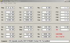
I’ll use Woody’s RCF LF15G401 TH as an example because this driver is one of few drivers on the market that have an Xlim that is more then 3 times the Xmax .
.
Driver specs RCF LF15G401:
Xmax = 8.7mm
Xlim = 32mm
AES 1300Watt
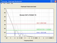
The results from HornResp of Woody’s design show us you will need 340 Watt to reach the drivers Xmax of 8,7mm. If you compare that with the ‘cheap’ Eminence 3015LF Xmax of 9,6mm it would mean the Eminence is a better driver in this horn
To reach the RCF’s Xlim of 32mm you’ll need 4560watt
-3dB from Xlim = 2280 watt (22,6mm excursion) = Max PWR
-6dB from Xlim = 1140 watt (16mm excursion) = Cont. PWR (Music Program)
You can see that the -6dB point from Xlim of 1140 Watt is still under the AES power rating of 1300 Watt. This means the coil is more then able to handle this load and still have the 9dB crest factor. Physically speaking you can see the -6dB from Xlim is only 50% of the maximum excursion and still very save to use.
There are only two questions left:
1.) Is the driver physically able to handle these forces in a horn load? This question can only be answered in a real life set-up.
2.) How much Pwr compression and THD this excursion beyond its Xmax will cost? Also this question can only be answered from measurements in a real life set-up.
So if you want to compare this RCF driver with the Eminence 3015LF it is ‘not fair’ to use the Xmax as the guideline for the drivers max capabilities. Also it explains why the high price of the RCF is somehow justified...
Take the Xlim of the driver and watch the power you need to get there in HornResp. Then go – 6dB in power from that point. As long this number stays under the EAS continue power rating of the driver you can use this as your new Continue PWR guideline. Use the -3dB point under the Xmax as the Max Power for your design (as long this number stays under the max pwr rating of the driver).
I’ll use Woody’s RCF LF15G401 TH as an example because this driver is one of few drivers on the market that have an Xlim that is more then 3 times the Xmax
. Driver specs RCF LF15G401:
Xmax = 8.7mm
Xlim = 32mm
AES 1300Watt
The results from HornResp of Woody’s design show us you will need 340 Watt to reach the drivers Xmax of 8,7mm. If you compare that with the ‘cheap’ Eminence 3015LF Xmax of 9,6mm it would mean the Eminence is a better driver in this horn
To reach the RCF’s Xlim of 32mm you’ll need 4560watt
-3dB from Xlim = 2280 watt (22,6mm excursion) = Max PWR
-6dB from Xlim = 1140 watt (16mm excursion) = Cont. PWR (Music Program)
You can see that the -6dB point from Xlim of 1140 Watt is still under the AES power rating of 1300 Watt. This means the coil is more then able to handle this load and still have the 9dB crest factor. Physically speaking you can see the -6dB from Xlim is only 50% of the maximum excursion and still very save to use.
There are only two questions left:
1.) Is the driver physically able to handle these forces in a horn load? This question can only be answered in a real life set-up.
2.) How much Pwr compression and THD this excursion beyond its Xmax will cost? Also this question can only be answered from measurements in a real life set-up.
So if you want to compare this RCF driver with the Eminence 3015LF it is ‘not fair’ to use the Xmax as the guideline for the drivers max capabilities. Also it explains why the high price of the RCF is somehow justified...
Attachments
Last edited:
Frequently, x-max is one-way, but x-lim is peak-to-peak.
Look at the spider to top-plate clearance to be sure (usually the first thing to hit).
With the RCF LF15G401 the coil will come out of the gap completely if you're not careful.
I don't think it's safe to drive beyond the 50% BL point, about 11.5mm for this driver. It will be severely compressed at this point too, and the spectral balance will be skewed as the mids and HF continue to get louder.
Hi djk, you beat me to it ,
From the LF15G401 spec sheet:
"...Maximum excursion before damage (peak-to-peak): 52mm ...Voice coil winding depth(Hvc): 23mm ...Top plate thickness(Hg): 12mm ...Xmax (mathemactical=(Hvc-Hg)/2+Hg/4): 8.5mm"
It would be nice to see some Klippel data on this driver.
I would be very reluctant to put my name on a design that drives a woofer (this driver or any other one) near its Xlim, or its maximum input power, particularly in a tapped horn. At the impedance minima the cone seems to be so well controlled that it is basically not moving, not an ideal condition for high power handling. Below the lower cut-off or design corner the driver is unloaded resulting in rapidly increasing excursion, not what you want to see if you are anywhere near Xlim in the passband.
All that being said, the LF15G401 looks like a very fine driver for a tapped horn. I fiddled around with Woody's Hornresp model a little, I just like what reducing the throat to as little as possible does for this one.
Regards,
,From the LF15G401 spec sheet:
"...Maximum excursion before damage (peak-to-peak): 52mm ...Voice coil winding depth(Hvc): 23mm ...Top plate thickness(Hg): 12mm ...Xmax (mathemactical=(Hvc-Hg)/2+Hg/4): 8.5mm"
It would be nice to see some Klippel data on this driver.
I would be very reluctant to put my name on a design that drives a woofer (this driver or any other one) near its Xlim, or its maximum input power, particularly in a tapped horn. At the impedance minima the cone seems to be so well controlled that it is basically not moving, not an ideal condition for high power handling. Below the lower cut-off or design corner the driver is unloaded resulting in rapidly increasing excursion, not what you want to see if you are anywhere near Xlim in the passband.
All that being said, the LF15G401 looks like a very fine driver for a tapped horn. I fiddled around with Woody's Hornresp model a little, I just like what reducing the throat to as little as possible does for this one.
Regards,
Attachments
Guys you have a good point there! One rectification, it looks like I have mixed up the specs from the LF15N541 with those of the LF15G401 my mistake...
RCF - LF15N451
Max excursion before Damaga (peak-peak) = 64mm
Coil Depth = 25mm
Top plate thickness = 15mm
Xmax = 8.7mm
BL = 33.5 TM
Qms = 4.2
Qes = 0.19
Qts = 0,18
Mms = 171gram
Fs = 35Hz
Re = 5.1Ohm
AES Pwr = 1300W
Max Pwr = 2600W
Quote Oliver: "At the impedance minima the cone seems to be so well controlled that it is basically not moving, not an ideal condition for high power handling".
Nope, not if you just play continues sine waves at the impedance minima for hours... But even D&B is filled with other frequencies and these sine wave bass lines do change from time to time... But I admit using the AES power standard is tricky since its bandwidth is limited and measured from a basreflex cab (AES2-1984 standard: 50-500Hz, 2 Hours min and max 100 hours of pink noise - RCF used in the past the 100 hours standard).
(And thanks Oliver for the diagram)
! One rectification, it looks like I have mixed up the specs from the LF15N541 with those of the LF15G401 my mistake... RCF - LF15N451
Max excursion before Damaga (peak-peak) = 64mm
Coil Depth = 25mm
Top plate thickness = 15mm
Xmax = 8.7mm
BL = 33.5 TM
Qms = 4.2
Qes = 0.19
Qts = 0,18
Mms = 171gram
Fs = 35Hz
Re = 5.1Ohm
AES Pwr = 1300W
Max Pwr = 2600W
Quote Oliver: "At the impedance minima the cone seems to be so well controlled that it is basically not moving, not an ideal condition for high power handling".
Nope, not if you just play continues sine waves at the impedance minima for hours... But even D&B is filled with other frequencies and these sine wave bass lines do change from time to time... But I admit using the AES power standard is tricky since its bandwidth is limited and measured from a basreflex cab (AES2-1984 standard: 50-500Hz, 2 Hours min and max 100 hours of pink noise - RCF used in the past the 100 hours standard).
(And thanks Oliver for the diagram)
Last edited:
Again
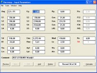
Okay using the same method as before but then with the good specs of the RCF LF15G401. The HornResp inputs I use from: Woody1 given in post 22 (which I used before)
http://www.diyaudio.com/forums/subwoofers/170749-15-tapped-horn-rcf-3.html
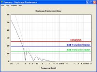
To reach the RCF’s Xlim of 26mm you’ll need 3000watt
-3dB from Xlim = 1500 watt (18,3mm excursion) = Max PWR
-6dB from Xlim = 750 watt (13,6mm excursion) = Cont. PWR (Music Program)
It looks like I’m not way off from your point Djk although admit in reality it would give severely compression from this -6dB Xlim point.
Oliver your model shows that the 1500W load would give an 36,6mm peak-peak excursion. Your model shows the coil would just come out totally of the air gap by 0.9mm ...
So yes, I still think you can use this method as a quick guideline, well at least for the -6dB point and changing it into the Maximum Effective Pwr.
Okay using the same method as before but then with the good specs of the RCF LF15G401. The HornResp inputs I use from: Woody1 given in post 22 (which I used before)
http://www.diyaudio.com/forums/subwoofers/170749-15-tapped-horn-rcf-3.html
To reach the RCF’s Xlim of 26mm you’ll need 3000watt
-3dB from Xlim = 1500 watt (18,3mm excursion) = Max PWR
-6dB from Xlim = 750 watt (13,6mm excursion) = Cont. PWR (Music Program)
It looks like I’m not way off from your point Djk although admit in reality it would give severely compression from this -6dB Xlim point.
Oliver your model shows that the 1500W load would give an 36,6mm peak-peak excursion. Your model shows the coil would just come out totally of the air gap by 0.9mm ...
So yes, I still think you can use this method as a quick guideline, well at least for the -6dB point and changing it into the Maximum Effective Pwr.
Attachments
Last edited:
what was the excursion @ 750 wats on the fury?
i stil think for comparison to use the mathematical x-max since we are only using pro drivers imo.
probably more than I'm comfortable with....
I can tell you that the natural cooling of a TH, as opposed to the sealed chamber of a FLH makes a big difference heat wise. I've never felt any heat in the frame of a 3015lf in a TH. FLH is a MUCH different story.
so I don't know if PE can be pushed a bit in a TH, and I don't know how far you can push past xmax... However because the driver is in the mouth, hopefully you'll hear when you're about to go too far... before it actually happens.
I'm chicken, and never run my subs that hard...
Hi Oliver,
Oliver your model and Djk’s suggestion only told me my method didn’t work because I used the data of the RCF LF15N451. I made new calculations in post # 145 to show you what I had done wrong. Anyways, I hope you and Djk want to consider the following:
There is NO relation between Xmax of a driver and the Maximum Power you can use to amplify a driver in a Tapped Horn. What I do try to prove here is that there is a correlation between the drivers Xlim and the maximum power you can use.
In most concepts I see people use the Xmax as the guideline for safely powering the driver. In my view this Xmax ‘standard’ will underrate ‘latest generation’ drivers regarding the more conventional type of drivers. The latest generation have more Xlim which is often more then 2 times the Xmax. ‘Old’ drivers have an Xlim that is just 1.5 times the Xmax.
I see it this way and please forgive me (and please do correct me) for the use of the wrong terms or theories. After Djk's remark about the danger when the coil leaves the gap I did some re-calculations. Instead of -6dB you need to use -7dB.
So my new method: Max (Effective) Pwr of a driver in TH’s = the power (Watt) you need to reach Xlim multiplied by 0.44668359215096315 (-7dB) in electrical power.
Max Power = Xlim -7dB
With Maximum (Effective) Pwr I mean the point from where severely power compression seems to start with all side effects (high THD, temp rise of the voice coil and so on). Although the better engineered drivers will stand a -6dB or even -5dB point from Xlim. This will make the voice coil come out of the gap but since most modern drivers do have a longer 'pipe' then the voice coil itself it will keep the coil in line with the gap. However, the extra energy will not result in (much) more max SPL but it will raise the lower signals within the music as part of compression effect.
1.) The Xlim of the driver is the result of the BL factor (motor) and mechanical data (like gap height and Coil height) of the driver.
2.) The loading from a TH determines when and where the theoretical maximum excursion (Xlim) of the driver is reached.
So in case of miss-loading, bad TH drivers or less efficient designs the -7dB point will still work since the Xlim will be reached with less Power. In case the air gap or coil height are different the outcome of the -7dB point changes in correlation. Also if you change the TH’s expansion rate the Xlim will shift and with that its -7dB point. In other words, if any of those parameters change the -7dB point changes in correlation with it.
Therefore, in my opinion the -7dB method works safely and gives more accurate results then the Xmax guideline.
Djk and Oliver, does my method make sense or am I looking in the wrong direction and if so please explain me...
Last edited:
Hi Djim,
I have no doubt that the best of the modern drivers are setting new targets for designers to shoot for. The way I understand it you are looking to establish a method applicable to a specific type of enclosure (tapped horn) for a specific range of transducers (modern large Xlim professional subwoofer drivers), and I don't know enough about it to agree or disagree, it seems unlikely that there would be one universally applicable formula.
As to Xlim, I see it as an exclusively mechanical parameter. I just tried to point out that by the time you reach Xlim you are so far magnetically decoupled between the gap and the coil that you basically don't have an electromechanical transducer anymore, you're just running on inertia and suspension spring.
The problem I see with the TH is that after all this time nobody has had the means, or time, to provide some meaningful data on the actual excursion in a TH under maximum load conditions. To the best of my knowledge the present simulation tools do not provide that data.
But, don't let me discourage you, and keep on providing any information you want to share.
Regards,
djim:
I took your -7db rule and applied it to the ss15 and the 3015lf.
63v(500w) keeps you under 9.6mm xmax, and it takes about 109v(1500watt) to hit the 17mm xlim.
.4467*1500 = 670watt. That is about 73v(670watt) and about 11.5mm xmax in the passband. Scott says he'll push his to about 750 watts, (3015lf is PE rated 450watt rms, 900 peak)
so I guess in this case -- your math seems to line up pretty well with at least one known real world example. Hornresp says you get another db or bit more but that's all.
How this translates to a driver with xlim at 3 times xmax? not sure.
Hi Oliver,
Quote Oliver: “The way I understand it you are looking to establish a method applicable to a specific type of enclosure (tapped horn) for a specific range of transducers (modern large Xlim professional subwoofer drivers)”
That is almost exactly what I’m after (actually all the time here on this forum). I prefer to re-arrange your phrase into: I try to establish working methods applicable to a specific type of enclosure (tapped horn in this case) for all transducers. My method should not work any different for any kind of PA bass driver. However, it does show the advantages of the modern techniques used by B&C, RCF, 18Sound and others. Also if this method works I think you can transfer it to other types of cabinets. The only difference will be you need another number then -7dB.
Quote Oliver: “And I don't know enough about it to agree or disagree, it seems unlikely that there would be one universally applicable formula”
I really appreciate your honesty about your doubts and especially that you don’t wave it away as impossible. I'm sorry if any of my posts do sound lecturing cause that's not my intention. Oliver, I’m not sure myself about this method although I’m sure there is NO relation between Xmax and Max Pwr for TH's. Xmax doesn’t change under different loadings so it doesn't add anything in my view to the max pwr.
I know, the relation between Xlim and Max Pwr looks funny at first that’s why I call it correlation instead of relation between Xlim and Max (Effective) Power. I also hope someone can add or help me out with this.
Quote Oliver: “The problem I see with the TH is that after all this time nobody has had the means, or time, to provide some meaningful data on the actual excursion in a TH under maximum load conditions.”
The problem with ‘meaningful data on the actual excursion’ in TH’s is difficult to provide for ‘armatures’. It costs extra investment if you want to produce very accurate data. Indeed it's also very time consuming. However, my method is based on the theoretical model from HornResp and in reality the excursion will be lower.
In my opinion this is caused by several damping factors; cone damping, electric damping (as the cone moves slower then the signal), and system damping (panel-flex, non-gentle bending and obstructions). Therefore I’m still believe you can use -5dB from Xlim with good engineered drivers from the top range.
Quote Oliver: “To the best of my knowledge the present simulation tools do not provide that data.”
I disagree here. I’m not inventing a new wheel here. I just use the tools already provided by HornResp. I see it this way:
Input versus output = efficiency. The TH (or Horn) is more efficient. So the max output is reached earlier then in a bass reflex for instance. This gain factor is set by two things, expansion and directionality. This means bigger cone excursion with the same energy input in relation to a certain gain factor. Xlim therefore is linked to gain factor and Xmax isn’t. Xmax is a vast number that doesn’t change with different type of loadings. Xlim does change with different loadings. So that's how I link Xlim and max input together.
It isn’t rocket science or horn voodoo. The gain factor shows up in HornResp as cone excursion vs SPL. It also shows the dips and peaks caused by impedance of the system and its harmonics. All these factors influence the excursion and tell you what the driver is doing. As Djk added to look carefully at the point where the coil leaves the gap (or does hit the backplate) I looked for a factor that includes these events. Of course if manufacturers do deliver wrong data it won’t hold, but the whole design would fail anyway. That’s why I don’t like semi pro drivers since they use unknown measuring methods to get data.
However, if I got Djk’s suggestion right, I think he meant that air gap height and coil height are not (always) direct related to Xlim. This suggestion is something I need to look into. If there is no relation between those facts my method fails. I haven’t found any standard yet how manufactures produce the number for Xlim data and which factors are responsible for it.Till that time I’m not sure at all...
I would calculate the 50% BL point and consider that the worst case operating limit.
50% BL will probably give 6dB of power compression, and the Qts will have risen dramatically, causing the cabinet to be mis-tuned.
I frequently pretend the Qts of the driver is about 15%~20% higher than it actually is. This is like pretending the motor isn't as strong as it really is. The design may sound just a bit 'lean' at low volume levels, but as you begin to 'thump' it a bit it comes into design alignment and 'blooms'. Remember, x-max is usually specified at the 70% BL point where the Qts is higher.
djim:
I took your -7db rule and applied it to the ss15 and the 3015lf.
63v(500w) keeps you under 9.6mm xmax, and it takes about 109v(1500watt) to hit the 17mm xlim.
.4467*1500 = 670watt. That is about 73v(670watt) and about 11.5mm xmax in the passband. Scott says he'll push his to about 750 watts, (3015lf is PE rated 450watt rms, 900 peak)
so I guess in this case -- your math seems to line up pretty well with at least one known real world example. Hornresp says you get another db or bit more but that's all.
How this translates to a driver with xlim at 3 times xmax? not sure.
Thanks Jbell, try the RCF LF15N451 that I used and mixed up with woody's design. It has a Xlim which is 3.6 times the Xmax.
Scott's practical findings show it is possible but there is one big but! Eminence! They don’t provide AES standard power ratings. It's not clear to me which measuring standard they use exactly. I also lift my eyebrows when I see a relative light motor and lightweight moving mass combination. To me that isn’t a very good starting point for low frequencies at high volumes. Especial if you want to reach the 30Hz target what this subject is about in the first place.
On the other hand it looks like his 750Watt seems to make up some damping/compression factors which will lower the excursion in real world situations. I think that is no problem as long the driver can handle the rise in temperature and forces that are hitting the cone.
I would calculate the 50% BL point and consider that the worst case operating limit.
50% BL will probably give 6dB of power compression, and the Qts will have risen dramatically, causing the cabinet to be mis-tuned.
I frequently pretend the Qts of the driver is about 15%~20% higher than it actually is. This is like pretending the motor isn't as strong as it really is. The design may sound just a bit 'lean' at low volume levels, but as you begin to 'thump' it a bit it comes into design alignment and 'blooms'. Remember, x-max is usually specified at the 70% BL point where the Qts is higher.
Djk your method makes sence but why do companies develop and build drivers with an extended Xlim > 1.4 times the Xmax? This extension can’t be used effectively in your view. Or perhaps, do they have a ‘trick’ to ‘extend’ their 50% BL point? Like you use but then by 'over' powering the motor?
(nice design tip btw, thnx)
Last edited:
imo,the x-limit is (like oliver said)just a mechanical limit.
it means you can exceed x-max without botteming the coil or tearing the surpension.
this means they can have more abuse without destroing your speaker,
however at that point power compresion and destortion com/are in to play.
the question is how much of this distortion is "acceptable"
i think that wil be desided bij the type of music played,and personal flavor.
that,and with the huge power ratings nowadays ,pro drivers are hard to destroy ,nevertheless they can and will at some point.
i'm like jbell ,i dont like to drive my subs much over the x-max.
Last edited:
Nobody wants failures and that’s the reason why I am looking for a method that gives the maximum and safe power input for a driver in a tapped horn. But after exchanging our information I have come to the conclusion that there is no wrong and right here.
Both methods are theoretical and have both their advantages and disadvantages. Both methods do not take into account that in real life situations the result is lower excursions!
The funny thing is that the more I calculate and read about other peoples real life findings that the Xlim method in reality meets around the predictions from the BL method…
The BL method:
Max Pwr = BL50% = Xmax x 1.4
The Xlim method:
Max Pwr = Xlim -7dB (electrical power)
Last edited:
I don't like the simplifications, magnet structures vary too much, and it's easy to do the math.
An example of your method failure is the Eminence sold by Martinsound as the #1844. It has 9.1mm x-max, but the top plate is only 7.93mm. By your method the 50% BL point should be 12.74mm. The 9.1mm is with the 70% BL method, so the 50% BL point would only be 11mm.
Maybe I just like being cautious.
An example of your method failure is the Eminence sold by Martinsound as the #1844. It has 9.1mm x-max, but the top plate is only 7.93mm. By your method the 50% BL point should be 12.74mm. The 9.1mm is with the 70% BL method, so the 50% BL point would only be 11mm.
Maybe I just like being cautious.
- Home
- Loudspeakers
- Subwoofers
- C/E/X PA Flat to 30 (FT30) PA TH Awesomeness