burnedfingers said:carlmart
You still haven't shown any proof what so ever. All you have posted are your opinions. Based on what?
And who said I was going to show any proof besides my opinion? They were based on my ear of course, and that of my friend's! For me that's proof enough, as the experience was quite controlled. Same record, same level.
And I don't have to prove anything to nobody, except to myself. This is not a contest.
The Chip Amplifiers forum is filled with people finding things similar to the ones I did.
This thread was about whether bypassing caps in PSUs improved things or not. Over that matter I haven't yet done any empiric testing to see what changed. It might be interesting trying that.
Hi,
I have come to the conclusion based on Carlmart's opinion and listening experience that a chipamp cannot be used as a wideband amplifier.
It's performance is crippled by the insistence on omitting sufficient smoothing between rectifier and chipamp.
It seems a shame that this is the only way to get good mid/treble performance.
There must be other ways.
Let's hear some other views on how to improve the chipamp or it will be tarred for ever.
AndrewT said:Hi,
I have come to the conclusion based on Carlmart's opinion and listening experience that a chipamp cannot be used as a wideband amplifier.
It's performance is crippled by the insistence on omitting sufficient smoothing between rectifier and chipamp.
It seems a shame that this is the only way to get good mid/treble performance.
There must be other ways.
Let's hear some other views on how to improve the chipamp or it will be tarred for ever.
Well, you didn't pay attention to my other comments: using a regulator and using a snubber on the supply seem to bring the mid and high frequencies back.
I didn't have the chance to prove those, particularly the snubber, because of other things I was and am involved with. But I promise I will.
Though think of something: Jeff Rowland built two extremely well regarded power amps, using high capacitance supplies, with a design based on bridging/paralleling one of these chips, the LM3886.
In fact that was the reason my friend and I were interested in finding out more about the gainclones.
So I wouldn't disregard chipamps so easily. There's an LM3886 design by Mauro Penasa that uses two 10000uF caps in the on-board supply, and nobody reports nothing is missing.
Once again: when I mentioned the chip amps, was as an example for bypassing. The snubber was a solution that improved things in what seemed a limited design. The snubber was tried and refined until working best in that amp.
Bypassing can be tried with different parts, listening to what works best for a particular amp.
Isn't that what this hobby is all about?
Carlos
carlmart said:.......In the Chip Amplifiers there was a similar problem with Gainclones too, that seemed to sound muddy in mids and highs when you increased PSU caps beyond 1000uF, even if lows improved. Adding a snubber allowed using larger caps and brought back the missing mid-highs........
carlmart said:What we did was test some gainclones, same source and speakers, only changing the supply caps. On that test, when using the 1000uF capacitors the highs and mids were very good, and low frequencies were less controlled. When going to 2200uF or higher, the bass got tighter, but the mids and highs were less clear............We are not talking 50W or 60W here, which would certainly demand tenths of thousand uF to play properly. Probably 30W or so, which would be plenty in most circumstances. ...........In the Chip Amplifiers forum this matter found a third option: using a snubber......
I am glad you are now clarifying your stance.using a regulator and using a snubber on the supply seem to bring the mid and high frequencies back.
Your previous postings give the strong impression that all smoothing must be restricted to LESS THAN 2200uF (preferably <=1mF) and NO regulators.
It appears that part of your intended message is being mis-interpreted by me and others.
Do you want to explain fully in one posting how to build a good sounding chipamp that meets your performance criteria? Maybe post a schematic from transformer to speaker if you can/have one
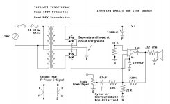
Chip amp - Basic version
I am sorry if I gave that impression. That was not my intention. I think an amplifier should respond with equal quality and should be wideband.
I will try.
The merit for many of the chip amp findings should go to Thorsten Loesch, who first suggested using some chip amps cloning the 47Labs Gaincard design. It was a highly regarded low power amp (20W), inverting layout, using the "minimum parts" philosophy of its Japanese designer.
So the T.Loesch basic design was inverting, used two bridges per channel (to improve ripple noise cancellation) and had no output coil or zobel.
AndrewT said:I am glad you are now clarifying your stance.
Your previous postings give the strong impression that all smoothing must be restricted to LESS THAN 2200uF (preferably <=1mF) and NO regulators.
I am sorry if I gave that impression. That was not my intention. I think an amplifier should respond with equal quality and should be wideband.
Do you want to explain fully in one posting how to build a good sounding chipamp that meets your performance criteria? Maybe post a schematic from transformer to speaker if you can/have one
I will try.
The merit for many of the chip amp findings should go to Thorsten Loesch, who first suggested using some chip amps cloning the 47Labs Gaincard design. It was a highly regarded low power amp (20W), inverting layout, using the "minimum parts" philosophy of its Japanese designer.
So the T.Loesch basic design was inverting, used two bridges per channel (to improve ripple noise cancellation) and had no output coil or zobel.
Attachments
AndrewT said:Hi,
I have come to the conclusion based on Carlmart's opinion and listening experience that a chipamp cannot be used as a wideband amplifier.
It's performance is crippled by the insistence on omitting sufficient smoothing between rectifier and chipamp.
It seems a shame that this is the only way to get good mid/treble performance.
There must be other ways.
Let's hear some other views on how to improve the chipamp or it will be tarred for ever.
I would be more glad if you based your conclusion on maybe a different opinion. Here's one example:
A customer in Cyprus chooses my GC monoblocks (with only 1000uF bypass caps) for bass amplifiers in multi amp system:
http://www.6moons.com/audioreviews/westernelectric/300b.html
" The Suprateks ran everything except the basshorns. Those were driven by a pair of AudioZone chip-amp monos. " ;-)))
Hi Peter,
I am only too glad to hear a variety of opinions on how to build chipamps properly.
I am ashamed to admit, but I could see no other way than to challenge Carlmart up front (even goad him), to get him to explain how he came to what initially appeared to be monstrous exaggeration of the benefits of omitting properly sized smoothing capacitance from the power supply. I am not convinced that the last posting is a true description of Carlmarts' tested assembly (it still shows +-2200uf between rectifier and chipamp and no regulator and no RC snubbers and only V+ to V- bypass).
Re your reference to 6moons:
Where, other than in the equipment listing, is the reference to those chipamps and how to wire them up?
I have read through a number of previous postings by yourself.
I cannot recall if you use only bypass (decoupling) in lieu of PSU smoothing or you advocate the use of both.
Can you enlighten?
I note the use of "bypass" implying smoothing elsewhere. Have I read that correctly?my GC monoblocks (with only 1000uF bypass caps)
Here's the review of that particular amp: http://www.6moons.com/audioreviews/audiozone/amp2.html
I'm using BG STD 1000/50 as main filter caps, bypassed by BG N 4.7/50. Later I switched to bypass only a negative rail, as I found doing it on both rails adds too much veiling to mids and highs.
I was a bit surprised myself seeing that article on 6moons, especially when the amps have been in a such good company of other equipment (my partner mentioned that DarTzeel have been also considered here).
Personally, I don't like to use any additional small bypasses on main filter caps, I always find them very manipulative. Although they may seem to improve things initially, in a long run it always seems like they destroy the "purity" of the sound. That's why I prefer to chose the main caps in a such a way that small bypasses are not needed.
One way to get "cleaner" sound is to use much smaller than usually capacitance. That may not work in all applications, however, from what I found it works in most cases.
BTW, those small GC chassis can only dissipate 5W of constant power into dummy load so why expect the caps to deliver more?")
I'm using BG STD 1000/50 as main filter caps, bypassed by BG N 4.7/50. Later I switched to bypass only a negative rail, as I found doing it on both rails adds too much veiling to mids and highs.
I was a bit surprised myself seeing that article on 6moons, especially when the amps have been in a such good company of other equipment (my partner mentioned that DarTzeel have been also considered here).
Personally, I don't like to use any additional small bypasses on main filter caps, I always find them very manipulative. Although they may seem to improve things initially, in a long run it always seems like they destroy the "purity" of the sound. That's why I prefer to chose the main caps in a such a way that small bypasses are not needed.
One way to get "cleaner" sound is to use much smaller than usually capacitance. That may not work in all applications, however, from what I found it works in most cases.
BTW, those small GC chassis can only dissipate 5W of constant power into dummy load so why expect the caps to deliver more?
Chip amp - PSU regulator
Then came a solution to the capacitance limit problem, or what happened if you went past the 1000uF limit: a high current regulator.
Several designs were tried, but the one that seemed more practical was based on the LM338 chip. You needed a transformer with separate secondaries for it, but that was also a requirement in the original PSU using two bridges.
The JLH supply used similar chips, but in the gainclone you could higher in output voltage, like +/-30v or slightly more.
http://www.tcaas.btinternet.co.uk/jlhnewps.htm
A tricky thing on this supply was the small cap that should be used at the output. Its implementation on the gainclone also gve better results if you splitted that 100uF cap, using 47uF on the supply and 47uF close to the chip power legs.
BTW: that small cap at the output seems to be a good tip also for the 3X7 chips.
Carlos
A high current regulator had it's own limitations and in the end it did not bring any improvement (unless one used really weired speakers with those amps). I sold mine as soon as I built it:
http://www.diyaudio.com/forums/showthread.php?s=&threadid=39582
http://www.diyaudio.com/forums/showthread.php?s=&threadid=39582
Chip amp - Snubber
Well, I am glad Peter Daniel also came give me a hand here. His designs are very good.
Next step on this gainclone improvement came through the findings of CarlosFM, who had also worked on the LM338 regulator as a way to improve on the limitations.
http://www.diyaudio.com/forums/showthread.php?postid=627945#post627945
His tests with snubbers were quite intensive, until he found a combination of capacitor and resistor that seemed to get best results.
http://www.diyaudio.com/forums/attachment.php?s=&postid=534018&stamp=1103139431
This all generated quite hot debates at the forum. But it seemed to work for many.
Chip amp - Buffer
One problem seemed to be using an inverting design for the gainclone, which seemed to sound a bit better than a non-inverting. But also brought some maladies, like making the design much dependent on what came before it.
A buffer was a way out, and there were several good suggestions for that. Like Nuuk's three-transistors, or the OPA637 or some others.
For this I already built a board for, using the 637, but I didn't test it yet.
So far so good for a long walk.
If anyone goes have a look at the Chip Amp forum you will find many solutions now, from very small to complete amps, like those by Mauro Penasa.
Whatever your preconceptions may be you should forget them for a moment and give any of those designs a try.
Single, paralleled, bridged, unregulated, regulated, snubbered, buffered. All seem to sound different, so you may take your pick.
Carlos
A very good solution IMO is (if you really don't care about space) using large polypropylene motor RUN caps (say 100uf/400V or so) closest to the amp board itself - found at your local electrical shop. They're industrial standard and have pretty good specs - say they're comparable to Solens but cheaper. It really cleans up the sound whilst keeping the musicality as opposed to bypass caps which some may find harsh or lacking 'life'. Mix these with a CLC filter in the main supply (say 0.5R/10A continous for the choke) and you get a killer combination.
lucpes said:A very good solution IMO is (if you really don't care about space) using large polypropylene motor RUN caps (say 100uf/400V or so) closest to the amp board itself - found at your local electrical shop. They're industrial standard and have pretty good specs - say they're comparable to Solens but cheaper. It really cleans up the sound whilst keeping the musicality as opposed to bypass caps which some may find harsh or lacking 'life'. Mix these with a CLC filter in the main supply (say 0.5R/10A continous for the choke) and you get a killer combination.
Yes. Thorsten Loesch (or his alter ego Kuei Yang Wang) always grunted at using regulators or large capacitance on the gainclone. But favoured long CLC networks as a better supply.
In his tube designs there was always place for large polypropylene caps.
Large inductors and polyprops are difficult to get over here (Brazil), so I tend to prefer solutions like the snubber and RC networks.
- Status
- This old topic is closed. If you want to reopen this topic, contact a moderator using the "Report Post" button.
- Home
- Amplifiers
- Solid State
- Bypass caps on power supply