Another look and perhaps an idea?
Capslock: Thanks for that information.
Now what if one decided on one form factor -- say 2*1.25mm just as an example. Then one could stack a large value cap on top of a bypass on top of a high frequency unit. It would be a triple height setup with minimal real estate.
Anybody looked into that?
Petter
FYI: big Z5U ceramics are available at Digikey
PCC2244CT-ND
is a 22 uF 16 V Z5U in a 1812 package, so it's big, it is expensive (approx $36/10 pcs), but they do have it.
Also might want to consider as a large cap something like the Panasonic Specialty Polymer caps, eg
PCE3270CT-ND
100 uF 8 V 7.3 mm X 4.3 mm X 4.2 mm,
15 milliOhms at 100 kHz,
$7.42 each or $41.93 for 10
(gotta wonder who cooks up these crazy pricing schemes.)
Gentlemen, thanks for your kind comments! Glad this work can be of any use.
Yes, the electrolytic is somewhat bulky, but, as Einstein said, all is relative") . The Panasonic FC is "only" 250 mils (6.3 mm) in diameter. Moreover, I found this through-hole part to be very useful here to provide additionnal grounding vias to minimize return path, provided you use through-plated holes... I know, it's not obvious for DIYers like us, but through-plated holes can be easily made using this technique (look for "through-plating" - and yes, the pencil tip trick is very efficient ), based on a Multicore accessory, available from Farnell...
. The Panasonic FC is "only" 250 mils (6.3 mm) in diameter. Moreover, I found this through-hole part to be very useful here to provide additionnal grounding vias to minimize return path, provided you use through-plated holes... I know, it's not obvious for DIYers like us, but through-plated holes can be easily made using this technique (look for "through-plating" - and yes, the pencil tip trick is very efficient ), based on a Multicore accessory, available from Farnell...
Back to the caps now I know it's not easy to navigate through all the curves I posted, but have a look here, on the top graph. I've compared a 100nF/X7R/0612 // 220nF/X7R/0805 // Murata 22uF/1210 with (5V_23_dBV.dat) and without (5V_24_dBV.dat) the electrolytic in the HF region. The 'lytic cap is apparently not mandatory, but I really can't say without any listening tests. In the LF region (here, top graph), it somehow appears that the 'lytic has to be there, since it does a great job in the 50 MHz region.
To sum up about the 'lytic, I should say than you could go without it in purely digital bypassing (but personnally I'd keep it), but for bypassing DAC chips, it is mandatory IMHO...
As stated in a previous post, the very small value NPO/COG caps are apparently useless in this configuration. 22uF or 4.7uF Murata cap does an amazing job in the > 500MHz zone, and the main point is to help it in the < 500MHz region. You must keep the low ESL 100nF/X7R/0612. I have curves (can post'em if requested) showing that the 100nF/0612 helps a lot in the intermediate zone. If you can get hold of a 220nF/0612 or a 270nF/0612 instead, it would be perfect (I wish I can get some to test), otherwise the best solution is to stack a 220nF/X7R/0603 on the top of the 100nF/0612, and keep the Murata...
But there's so many configurations left to test... I wonder if we will see the end
Hope this helps
Yes, the electrolytic is somewhat bulky, but, as Einstein said, all is relative
. The Panasonic FC is "only" 250 mils (6.3 mm) in diameter. Moreover, I found this through-hole part to be very useful here to provide additionnal grounding vias to minimize return path, provided you use through-plated holes... I know, it's not obvious for DIYers like us, but through-plated holes can be easily made using this technique (look for "through-plating" - and yes, the pencil tip trick is very efficient ), based on a Multicore accessory, available from Farnell...Back to the caps now
I know it's not easy to navigate through all the curves I posted, but have a look here, on the top graph. I've compared a 100nF/X7R/0612 // 220nF/X7R/0805 // Murata 22uF/1210 with (5V_23_dBV.dat) and without (5V_24_dBV.dat) the electrolytic in the HF region. The 'lytic cap is apparently not mandatory, but I really can't say without any listening tests. In the LF region (here, top graph), it somehow appears that the 'lytic has to be there, since it does a great job in the 50 MHz region. To sum up about the 'lytic, I should say than you could go without it in purely digital bypassing (but personnally I'd keep it), but for bypassing DAC chips, it is mandatory IMHO...
As stated in a previous post, the very small value NPO/COG caps are apparently useless in this configuration. 22uF or 4.7uF Murata cap does an amazing job in the > 500MHz zone, and the main point is to help it in the < 500MHz region. You must keep the low ESL 100nF/X7R/0612. I have curves (can post'em if requested) showing that the 100nF/0612 helps a lot in the intermediate zone. If you can get hold of a 220nF/0612 or a 270nF/0612 instead, it would be perfect (I wish I can get some to test
), otherwise the best solution is to stack a 220nF/X7R/0603 on the top of the 100nF/0612, and keep the Murata...But there's so many configurations left to test... I wonder if we will see the end
Hope this helps
Petter:
I think the demands for the DAC chip are different than the demands for the other chips in a DAC system. The DAC has high speed inputs and low speed outputs. It never has a need to suddenly drive a line, and therefore has no need to draw current quickly from the digital side. On the analog side, the output is relatively high current (+/- 1.2mA on the PCM1704), but there is no demand for fast current: 48kHz is boring.
The approach to decoupling in my DAC design -- which should by no means be considered authoritative, but is based on the best information I could gather from the literature -- is to decouple all fast digital circuitry from the power rails and ground, in order to keep the noise off of the rails. Note that the point is not to keep the noise out of the chip, but to keep the noise from getting onto the power lines in the first place.
So, the digital input receiver, the clock, and the digital filter are all highly bypassed using a big 100uF electrolytic, a 4.7uF fast ceramic, and a 100nF fast ceramic. This combination should supply those digital chips with their fast current demands, without putting a lot of noise onto the power and ground planes. The digital side of the DAC is similarly bypassed, just for good measure.
For the analog side of the DAC, I simply use a 100uF electrolytic and 4.7uF ceramic decoupler at each power pin. There is no need for the ultra-fast 100nF because the analog side has no fast output capabilities in the first place.
Regarding the PCM1730, it is very attractive because it reduces the $150 cost of the DC1704 and four PCM1704U-K chips to a single $10 chip, but I would not expect it to sound as good. the PCM1704 at least has better specs all around: THD, output accuracy, etc.
Won't this cause some amazing ground bounce?jwb said:The approach to decoupling in my DAC design -- which should by no means be considered authoritative, but is based on the best information I could gather from the literature -- is to decouple all fast digital circuitry from the power rails and ground, in order to keep the noise off of the rails. Note that the point is not to keep the noise out of the chip, but to keep the noise from getting onto the power lines in the first place.
The whole point of the decoupling system is to reduce ground bounce (and other noise). The gound and power planes have massive inductance. When the IC draws a sharp spike of current, this inductance causes a voltage between Actual Ground and the ground seen at the package pin. The decoupling capacitor exists to satisfy the current spike and have relatively little inductance, hence minimizing ground bounce.
I've never heard anyone claim that decoupling caps CAUSE ground bounce before.
I've never heard anyone claim that decoupling caps CAUSE ground bounce before.
Quick question:
Sorry if I missed it, but is there a particular reason why one wants smaller physical size for the smallest caps?
My reasoning given very tight areage budget is that a scheme where 2 caps were same size (SMT), for example 10u Murata stacked on top of same physical size 160nF Murata, Ruby or whatever. The particular Muratas can both be had in 0805 (2*1,25mm) so total area used is that area.
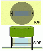
To add an electrolytic, it migh be useful to use the trick shown below to save space ... Width is usualla the big problem, and here we achieve 4 things: Minimal width (1,25mm), minimal space from pin to cap, smallest cap on bottom + minimum extra wiring to electrolytic.
Widt could be further reduced by mounting cap on its side ... but that would probably not fly with the inductance guys
I have shown two mounting methods -- half drilled guide hole (when you have conflicting stuff on the other side, and through hole.
Image: Top: top view, Bottom: Bottom view
Sorry if I missed it, but is there a particular reason why one wants smaller physical size for the smallest caps?
My reasoning given very tight areage budget is that a scheme where 2 caps were same size (SMT), for example 10u Murata stacked on top of same physical size 160nF Murata, Ruby or whatever. The particular Muratas can both be had in 0805 (2*1,25mm) so total area used is that area.
To add an electrolytic, it migh be useful to use the trick shown below to save space ... Width is usualla the big problem, and here we achieve 4 things: Minimal width (1,25mm), minimal space from pin to cap, smallest cap on bottom + minimum extra wiring to electrolytic.
Widt could be further reduced by mounting cap on its side ... but that would probably not fly with the inductance guys
I have shown two mounting methods -- half drilled guide hole (when you have conflicting stuff on the other side, and through hole.
Image: Top: top view, Bottom: Bottom view
Attachments
Help! Too Many Ceramic Bypass Choices
I'm replacing the audio output IC's in a Kenwood KT-6040 tuner (btw, one of the best ever, mostly sold in Europe). The factory circuit runs the output of an LA3450 mpx chip though an NJM4565D dual opamp and I'm going to replace that with a chip recommended by a friend who studies and listens to chips: an LM4562. He has told me the chip needs 0.1uF 25V minimum ceramic bypass from pins 4-8, 4-ground, and 8-ground. The chip is going to be socketed, so the caps will be soldered to the socket pins below the board. Beyond that, my friend refuses to say more.
Well this still leaves me a bewildering array of choices. Just looking at 100V caps (because I'm a fan of super spec overbuilding), 0.1uF, X7R (as seems to be recommended in this thread), Mouser shows 261 matches:
Multilayer Ceramic Capacitors MLCC - Leaded | Mouser
So please help me select the best. I'm not worried about cost so long as it's less than $1 per cap (arbitrary line in the sand) and in-stock. Here are some basic questions:
1) Would radial or axial leads be better?
2) What's the most desirable lead spacing, from 2.5mm to 7.6mm ?
3) Which is the most desirable type: Conformally Coated MLCC's, Dipped MLCC's, General Type MLCC's, High Reliability MLCC's, High Temperature MLCC's, Molded MLCC's ?
4) Which is the better manufacturer? AVX, Cornell Dubilier, Kemet, Murata, TDK, Vishay?
I arbitrarily decided to go with 100V, if I'd be better off going with 50V you can say that too. 50V is still over spec.
AND THEN I have to figure out the best DIP sockets. I won't bother with cyro sockets, but are gold plated a plus or a minus?
Using an SMD MLCC of the smallest size possible would be best, if you have to use a leaded one the smallest possible leads, the whole point is to minimise parasitic inductance. With this in mind the recommended voltage is more likely to give you a smaller case size and thus again lower inductance.
The best socket would be one that makes good contact so look for 3 or 4 point contacts in the pin sockets. Cyro is not going to do a thing!
The best socket would be one that makes good contact so look for 3 or 4 point contacts in the pin sockets. Cyro is not going to do a thing!
- Status
- This old topic is closed. If you want to reopen this topic, contact a moderator using the "Report Post" button.
- Home
- Source & Line
- Digital Source
- Bypass Caps for digital IC decoupling