Hi Reyntz,
Do you think you need that much heatsink for the diode bridges?
Chris
cant say for sure, but I dont think theres such big need for heatsink on bridge
I have never experienced a bridge even getting just a little hot
mounting on bottom plate have always been good enough
You will notice Nelson doing it that way too
double bridge ought to help too
cant say for sure, but I dont think theres such big need for heatsink on bridge
I have never experienced a bridge even getting just a little hot
mounting on bottom plate have always been good enough
You will notice Nelson doing it that way too
double bridge ought to help too
I agree with you
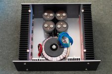
") , this is generally true for people who have adequate chassis size, mounting the bridge diodes on bottom plate is effectively making the whole chassis the heatsink for the bridges. Those bridges do get hot hence the metal backplate. In my case, I ended up with a compact chassis; 30cm conrad. From other people experiences a much bigger conrad than mine do get hot from an F5 with much less amps than BA2. As much as possible I would like to take heat away from the metal chassis, will also elevate the trafo a bit,
, this is generally true for people who have adequate chassis size, mounting the bridge diodes on bottom plate is effectively making the whole chassis the heatsink for the bridges. Those bridges do get hot hence the metal backplate. In my case, I ended up with a compact chassis; 30cm conrad. From other people experiences a much bigger conrad than mine do get hot from an F5 with much less amps than BA2. As much as possible I would like to take heat away from the metal chassis, will also elevate the trafo a bit, Attachments
Andrew,
How do you wire up the bridges in a dual configuration?
Also, how do you calculate the power dissipation per diode? I take it you don't use P=VI because the voltage phase is changing or is that bunk?
Let's say I have 300VA transformer into four diodes (rated each at 20A, 200V as it happens)from two 0-18V secondary windings?
That's 300/36 for the current from both secondaries isn't it, making 8.33A.
What would the voltage be across each of the diodes?
measure the voltage across one of the diodes in a bridge rectifier and you'll get close to 700mVdc.
If the diode is passing 1Aac or 1Adc then the diode must dissipate 700mW.
If the bridge has 4 diodes, half of which are passing at any one time then the bridge dissipation for 1Aac and 1Adc is 1.4W.
But the current is not AC. It is pulsed. This changes the dissipation.
Assuming sinewave current flow, my bridges passing 2.6Adc of bias should dissipate 3.64W.
Judging by how hot they got, I suspect actual dissipation was higher.
Thanks Andrew,
I'm going to use these Schottkys that I have (they fit neatly into the pcb) and I'll see if they run warm before I add a heatsink. I also have some higher rated HexFreds (which don't fit on the pcb). Ideally I'd like to listen to them both to see if they sound that different before settling on one or the other. I have used lower current devices before and I do prefer the HexFred design. They give a more analogue sound to my ears. Just to make things more complicated I have two 35A 200V bridges. The final decision will be ease of fitting I think.
Regards,
Chris
Take a look at the F5 PSU recommended by Nelson, it uses a dual bridge.Andrew,
How do you wire up the bridges in a dual configuration?
How do you wire up the bridges in a dual configuration?
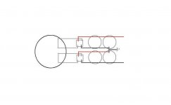
some will like the ground to "join" at the last cap pair, and some will "join" the ground at first cap pair
Attachments
Hi,
do not put the "ground" on either cap pair.
These links carry very high pulse currents back and forth to the transformer via the rectifiers.
Take a short, or longer, lead from the last pair and place the Audio Ground on this lead. This isolates the Audio Ground from the voltage variations that accompany the pulsing currents.
The reason for not tapping into the first cap pair is that what initially looks like a C//C filter is actually an rC(l+r)C filter.
The first r is the resistance of the transformer windings +wiring +rectifiers.
The l+r is the resistance and inductance of the lines between the capacitors. These impedances can be very small but they are not zero.
If one compares that rClrC to a more conventional two stage smoothing using RCLC then it is obvious that one never taps off smoothed DC from the first capacitor.
Always tap off the last C and keep the wiring from transformer to rectifiers and from rectifiers to smoothing short and twisted.
Last edited:
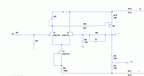
Are there any downsides on 'inverting' the frontend?
I mean flipping over the FE horizontally and using 2sk's in stead of 2sj's, leaving the CCS up to a 2sk and using an Nmos? The noise figures look the same for the sj and sk's. Or is this just a silly and bad idea?
The reason why is that I won't be needing the hard-to-get 2sj74's-2sj109's.
I have intensively searched on this forum but i could not find any thoughts on this... I have attached a rough sketch.
I mean flipping over the FE horizontally and using 2sk's in stead of 2sj's, leaving the CCS up to a 2sk and using an Nmos? The noise figures look the same for the sj and sk's. Or is this just a silly and bad idea
? The reason why is that I won't be needing the hard-to-get 2sj74's-2sj109's.
I have intensively searched on this forum but i could not find any thoughts on this... I have attached a rough sketch.
Attachments
[The reason for not tapping into the first cap pair is that what initially looks like a C//C filter is actually an rC(l+r)C filter.
The first r is the resistance of the transformer windings +wiring +rectifiers.
Andrew,
Does this mean that Nelson's 2R2K 'bleed' resistors on the BA2 power design should be placed as in the circuit diagram, before the first capacitor rather than after the 10uF cap which is where I've put mine or are you referring to series resistance?
Regards,
Chris
I was referring to series resistance in the rCrLC example I gave........Does this mean that Nelson's 2R2K 'bleed' resistors on the BA2 power design should be placed as in the circuit diagram, before the first capacitor rather than after the 10uF cap which is where I've put mine or are you referring to series resistance?
The charge bleed down resistors are a different animal inserted for a completely different reason.
Hi,
do not put the "ground" on either cap pair.
These links carry very high pulse currents back and forth to the transformer via the rectifiers.
Take a short, or longer, lead from the last pair and place the Audio Ground on this lead. This isolates the Audio Ground from the voltage variations that accompany the pulsing currents.
Hi AndrewT,
From which junction is the best place to tap the 'psu ground' which connect to the Thermistor to AC 'Earth'?
what a mix up of names/labels in the question.From which junction is the best place to tap the 'psu ground' which connect to the Thermistor to AC 'Earth'?
The PE (third wire in the mains cable) connects to chassis. I call this Safety Earth. I deliberately never call anything else "earth"
The Main Audio Ground connects to chassis.
Do not confuse terms, you will confuse us and your self.
what a mix up of names/labels in the question.
The PE (third wire in the mains cable) connects to chassis. I call this Safety Earth. I deliberately never call anything else "earth"
The Main Audio Ground connects to chassis.
Do not confuse terms, you will confuse us and your self.
My apologies if my query caused confusion. You have now an idea where my electronics understanding lies, My english is not that good aswell. This grounding thing is very confusing to me, as far as I know, there are 3 separate ground inside an Amplifier ( not sure ). " Safety Earth", "Power Supply Unit ground" and the " Main Audio Ground ". This is my understanding, please correct me if I'm wrong. The "Safety Earth" wire from the mains cables is bolted to the chassis, The "PSU ground" is the junction in the capacitor bank ( last pair of caps ) and the "Main Audio Ground" is a point ( star ground ) somewhere connected by wire to the PSU Ground. My question is : Where is the optimum point to put the thermistor? this is the thermistor that the other end is connected to safety earth. I guess to the capacitor bank ( last pair of caps ), not to the " Main Audio Ground"
Hi Andrew,
You said, " The Main Audio Ground connects to chassis." Thats not what it says in Mr. Pass schematics. please enlightened us.
Cheers,
ReyT
this is all correct..........This grounding thing is very confusing to me, as far as I know, there are 3 separate ground inside an Amplifier ( not sure ). " Safety Earth", "Power Supply Unit ground" and the " Main Audio Ground ". This is my understanding, please correct me if I'm wrong. The "Safety Earth" wire from the mains cables is bolted to the chassis, The "PSU ground" is the junction in the capacitor bank ( last pair of caps ) and the "Main Audio Ground" is a point ( star ground ) somewhere connected by wire to the PSU
The Main Audio Ground, or any part of it that is capable of passing Fault current, should be connected to chassis.
This connection should never carry significant current. Leakage current to Earth is about all it will pass in operating conditions.
Download the grounding article on our Home page and read it thoroughly.
I think all the answers are in there. Well, I can't think of any that could be left unanswered.
BA2 cascode front end
I have 3 pairs of cascode front end boards (requires one board per channel) that I will let go for what they cost me $10.00 per board plus shipping. The boards were laid out with 7.5mm spacing for Caps 205,206, and 208, which allow for higher voltage caps. Resistors R205,208,209,210,211 laid out for 3watt. The cascode transistors are laid out for ZTX550 PNP, with a voltage divider circuit for ZTX550 the remainder of the circuit is BA2 front end. The boards aree 3.9 in by 3.8 in.
I have 3 pairs of cascode front end boards (requires one board per channel) that I will let go for what they cost me $10.00 per board plus shipping. The boards were laid out with 7.5mm spacing for Caps 205,206, and 208, which allow for higher voltage caps. Resistors R205,208,209,210,211 laid out for 3watt. The cascode transistors are laid out for ZTX550 PNP, with a voltage divider circuit for ZTX550 the remainder of the circuit is BA2 front end. The boards aree 3.9 in by 3.8 in.
- Home
- Amplifiers
- Pass Labs
- Burning Amplifier BA-2