Any Update Mr. Pass?
I still have lots of those Motorola devices laying around. We are cleaning out my basement and she is asking questions about the silver things with two legs.
Any chance we will see a version that would allow me to use up a box of "regular" (MJ15024/25) transistors left over from my Audio Art days?
I still have lots of those Motorola devices laying around. We are cleaning out my basement and she is asking questions about the silver things with two legs.
I’d like to say a big thank you to all of you on this forum. A few nights ago I was going to throw in the towel over the BA-2. I couldn’t make sense enough of the circuit diagram to feel safe building it and then I sat down and read 35 pages of the BA-2 thread. I don’t know all the answers yet but thanks to you lot I’m going ahead and building it (if I can get hold of the circuit boards). Issues such as the a.c. secondary voltage required for a 25V d.c. output may seem straightforward to some of you but it was just another loose end to me.
What I would like now is a schematic for the wiring between the boards. Again this may seem obvious but not without experience it isn’t. Here’s my take on it.
The front-end input is stereo and I can see two inputs for balanced connections. There are the connections for two sets of power inputs, marked V-, GND, V+ and then on the left and right, D, OUT and something else I can’t read. Do D, and OUT, connect to D, and OUT on the bias board? I take it that all the connections marked V-, V+, CTL-, CTL+, OUT connect with the identically marked connections on the output board. However, where do I connect the power supply to the output board? Is it V-, and V+? Also, the output to the speaker terminals are from star GND, and OUT on the output board or do I have this wrong?
This is a great learning experience and I hope to live long enough to enjoy the end result so your help would be appreciated.
Regards,
Chris
We will be ordering the BA-2 board sets in a few days but it will be a while before they are manufactured and delivered. Realistically it will be about 6 - 8 weeks. When they are available they will appear as "in stock" at the diyAudio store ("store" in the colored band at the top of every page)
When you get the boards you will feel much better about wiring things up. The connections are labeled as to how to hook one board to another, and the other hook ups are not that complicated as I'm sure someone will explain. Worst case you can post a picture when you get stumped.
For now I would suggest accumulating the parts that you need. That takes a while..
Then getting the chassis of some sort built with heatsinks and power supply takes a lot of time too.
Populating the circuit boards and wiring it up takes surprisingly little time..
Mark
Last edited:
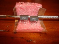
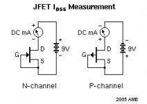
I bought two 2SJ109V's of Ebay (I know this is risky) from an USA source. I'm using the attached circuit to test the IDSS of them. I'm using a fluke 77 meter set to the 300ma scale. On one I get numbers that are 60.2 and the other is 59.8. This seems way high as the v series should be 10-20ma. Am I doing something wrong or have I been duped? The parts look real, and like they came out of a piece of equipment as legs are short like they have been cut out. Probably be another week before my 74bl and 170bl show up so something to compare them to.
Chad
Chad
Attachments
I’d like to say a big thank you to all of you on this forum. A few nights ago I was going to throw in the towel over the BA-2. I couldn’t make sense enough of the circuit diagram to feel safe building it and then I sat down and read 35 pages of the BA-2 thread. I don’t know all the answers yet but thanks to you lot I’m going ahead and building it (if I can get hold of the circuit boards). Issues such as the a.c. secondary voltage required for a 25V d.c. output may seem straightforward to some of you but it was just another loose end to me.
What I would like now is a schematic for the wiring between the boards. Again this may seem obvious but not without experience it isn’t. Here’s my take on it.
The front-end input is stereo and I can see two inputs for balanced connections. There are the connections for two sets of power inputs, marked V-, GND, V+ and then on the left and right, D, OUT and something else I can’t read. Do D, and OUT, connect to D, and OUT on the bias board? I take it that all the connections marked V-, V+, CTL-, CTL+, OUT connect with the identically marked connections on the output board. However, where do I connect the power supply to the output board? Is it V-, and V+? Also, the output to the speaker terminals are from star GND, and OUT on the output board or do I have this wrong?
This is a great learning experience and I hope to live long enough to enjoy the end result so your help would be appreciated.
Regards,
Chris
hi backbones,
you supposed all connections right. On the long output board all marks are on both sides so you could continue with another board and have six pairs of output devices. Clever made!
GND is the mark you could not read.
On the front board on one side were the voltage marks wrong they were inverse. They corrected it by hand, maybe in your delivery the fault is corrected....
best regards
The parts look
Chad,
they look like the fakes i got from A'af, and like the counterfeits i received through the group buy at the French HCFR forum.
Shiny legs and the even numbered ones are folded at a larger distance below the case.
In both cases, the fake ones were relabelled matched dual BJT Toshiba 2SA1349/2SC3381.
Also obsolete, with a steep NOS value in the west.
(unfortunately for moi, i bumped into sources in Asia that offer the matched BJT items for less than 50 cents)
Thanks for your replies everyone.
I've decided to use some 1200V 30A HexFred diodes on the power supply but has anyone had problems getting hold of these little beggars? I have been told over here in the UK by one supplier that I'll have to wait until Jan 2011. HexFreds seem generally in short supply. I've ordered some from DigiKey as a result but they wanted my first name before they could export them. I hope they send me some flowers now we're almost dating.
Regards,
Chris
each 2sk109 contains two jFETs.
Identify the legs and then measure one jFET, then measure the other jFET.
Do the same for the second k109.
I prefer to replace the ammeter with a resistor and then set my DMM to read DCV.
What size resistor do you recommend. I did measure both sides of the supposed Fet. They measure within about .5 ma at right around 59 ma depending on the temperature. I wish my 74's would get here so that I could compare them. I knew I was taking a chance buying the 109 but I really want to build as Neslon had intended. Another lesson learned the hard way. I want test them using Andrews method once more before I tell the vendor I believe he has fakes.
I have few 74's coming and 100 of the k170 in bl grade so should get proficient in matching.
Chad
you could use as low as 1r0 for the drain resistor. But you would have to be careful not to take the jFET overvoltage.
I would use 100r, that should drop between 600mV and 1200mV for BL grade jFET.
If you have a higher supply voltage for the testing you can increase the drain resistor to 1k0 or more.
Use the DMM to measure the voltage drop and then convert that mVdc to a current using I=V/R.
I would use 100r, that should drop between 600mV and 1200mV for BL grade jFET.
If you have a higher supply voltage for the testing you can increase the drain resistor to 1k0 or more.
Use the DMM to measure the voltage drop and then convert that mVdc to a current using I=V/R.
Yes, measure them again according to AndrewT's method.
Hopefully you have made a silly mistake in the measurement, but it is not looking good.
I have a fluke meter and it gives very accurate current readings. I have tried it measuring both ways and the error is well below 0.1%.
Fingers crossed you have made some sought of silly mistake in the first measurement.
Well doing it Andrews way unfortunately gave me the the same numbers. I've purchased fakes. I e-mailed the seller to let him know and asked for refund. We will see how he responds. Luckily I have some 74's that I can finish this project with. Any one know the status of Linear Systems 74's so this won't be in short supply any more?
Well good news, vendor immediately return the price of the 2sj109's and shipping to my Papal account. Lesson learned about buying semiconductors on Ebay. Seller had 99.8% rating. I dont think he realized what he was sold. I now believe the 109 is a piece of history in the diyaudio world.
Thank you to everyone here with helping confirm my readings with a few different methods.
Chad
Thank you to everyone here with helping confirm my readings with a few different methods.
Chad
2SJ74 / 2SK170 replacement
We don't need to be scared, Toshiba has already launched successors for J74 and K170 type JFET's in slightly smaller packages but with the identical chips and the same pin outs. NP is aleady using these types.
2SJ108 replace 2SJ74
2SK370 replace 2SK170
Please ask your dealers.
Unfortunately for the dual JFET'S 2SJ109 and 2SK389 no successors exist.
But matching is quit easy using the methodes described in this tread.
Gerd
- Home
- Amplifiers
- Pass Labs
- Burning Amplifier BA-2