Generg, I congratulate you on the prize!
I would like to call attention to my little quiz game in one, to which even a hint did not come till now,!
http://www.diyaudio.com/forums/lounge/130753-my-thoughts-nothing-else-8.html#post2018193
You never get me here seriously. (Respect ones who is exceptions.)")
It is not needed many times certainly.
Wacky Gyuri
I would like to call attention to my little quiz game in one, to which even a hint did not come till now,!
http://www.diyaudio.com/forums/lounge/130753-my-thoughts-nothing-else-8.html#post2018193
You never get me here seriously. (Respect ones who is exceptions.)
It is not needed many times certainly.
Wacky Gyuri
hi Gyuri,
no reaction is unpleasant!
I looked: one common thing could be:
"The Rashomon effect is the effect of the subjectivity of perception on recollection, by which observers of an event are able to produce substantially different but equally plausible accounts of it. A useful demonstration of this principle in scientific understanding can be found in an article by that name authored by Karl G. Heider.[1]"
I saw the film twenty years ago, I was impressed...!
I did not read Faulkners novel!
have a nice evening ....
,no reaction is unpleasant!
I looked: one common thing could be:
"The Rashomon effect is the effect of the subjectivity of perception on recollection, by which observers of an event are able to produce substantially different but equally plausible accounts of it. A useful demonstration of this principle in scientific understanding can be found in an article by that name authored by Karl G. Heider.[1]"
I saw the film twenty years ago, I was impressed...!
I did not read Faulkners novel!
have a nice evening ....
Gerd, I welcome you!
I decided so, you are the winning competitor.
Since the statement, which you found, is valid for both works.
Please, write your home address to me, where I shall send it to you the two LU1014 J-FETs.
I aggravate your existing infection by this of course.
You will be obliged to build one of the ZV9 or F3.
Wacky Gyuri
Dear Gyuri,
that is really a surprise!
I thank you very much for your opportunity to try an F3!
Oh, you heard about my infection! I suppose you are more infected by philosophy! Nobody writes in this forum things like you! an I am afraid it is difficult to be a partner for you.
What did you build in electronics?
hi Zen Mod,
maybe I just heard half of the heaven J2 promises....
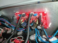
I got tea-bags semisouth and put them together with the semisouth I got from magura in a BA-1. I left the IRF240 on the negative side doing the job as a current source and ,like Nelson would say, not to spoil the performance of the output stage by the gainstage I changed the IRF610 by a semisouth R100.
Wonderful performance, more details, voices totally different and subtle.
So I can wait for J2 in any version much better!
maybe I just heard half of the heaven J2 promises....
I got tea-bags semisouth and put them together with the semisouth I got from magura in a BA-1. I left the IRF240 on the negative side doing the job as a current source and ,like Nelson would say, not to spoil the performance of the output stage by the gainstage I changed the IRF610 by a semisouth R100.
Wonderful performance, more details, voices totally different and subtle.
So I can wait for J2 in any version much better!

hi tea-bag and Zen Mod ,
Allow me a question. You are both longer occupied with substituting IRF with SS.
Is there a general recommendation?
I ask because of the replacement of IRF 610 in the gainstage of BA-1. Is for instance, more bias current advised?
please excuse this simple question, I am reading parallel all what Nelson wrote and try to understand it.....
and Zen Mod , Allow me a question. You are both longer occupied with substituting IRF with SS.
Is there a general recommendation?
I ask because of the replacement of IRF 610 in the gainstage of BA-1. Is for instance, more bias current advised?
please excuse this simple question, I am reading parallel all what Nelson wrote and try to understand it.....
..... one answer I found from Nelson, corresponding to Mini-Aleph, I suppose, (correct Tea-Bag?) was
...."The R100 has a lower Vgs than the IRFP240, so you need to
lower the value of the resistance from the Drain of Q1 to V- in
to bias it correctly. I use a potentiometer there...."
things go on!
...."The R100 has a lower Vgs than the IRFP240, so you need to
lower the value of the resistance from the Drain of Q1 to V- in
to bias it correctly. I use a potentiometer there...."
things go on!
Not sure here about the IRF610,
but based on other statements, lowering value of P201 might bake the output sound better. This is based on his recommendation on the Aleph-J of lowering R7 on Aleph-J schematic. The lower Vgs of the R100's means that we dont need 5v across it, can be lowered down a bit. Of course keep checking offset when changing. Get it lower and listen, see if it sounds better.
but based on other statements, lowering value of P201 might bake the output sound better. This is based on his recommendation on the Aleph-J of lowering R7 on Aleph-J schematic. The lower Vgs of the R100's means that we dont need 5v across it, can be lowered down a bit. Of course keep checking offset when changing. Get it lower and listen, see if it sounds better.
hmm.......
"If the gate voltage is above the threshold voltage (lower figure), the transistor is turned on, due to there being many electrons in the channel at the oxide-silicon interface, creating a low-resistance channel where charge can flow from drain to source. For voltages significantly above threshold, this situation is called strong inversion. The channel is tapered when VD > 0 because the voltage drop due to the current in the resistive channel reduces the oxide field supporting the channel as the drain is approached.
hm,hm ...
Vgs is 1v for the SSR100 I put on the place of the IRF610 now and the Vgs of the SSR100 implemented in the outputstage is 1,1V for each SSouth.I suppose these values are O.K. for SSR100 in action.
Is there anybody who can confirm that.....
or tell me what is else important?
happy generg
Last edited:


hi BA-1 experts,
do I understand Nelsons hint right, when I cancel the 10uF cap (for trial) I have to omit the positiv branch of biasing, but keep the negativ and I use the gainstage pot to put the output to zero?
The problem for me is to reverse Nelsons statement logically correct for the opposite case he mentioned.
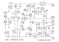
"Assuming you use C203 as recommended, you will also want the positive bias network consisting of R212, R213, R214, Z201, C209, and P202. C203 and all these parts are absolutely essential if you decide to use the output stage as a stand-along power buffer. The purpose of this circuitry is to provide a positive constant bias voltage to the input of the bank of power Mosfets which sets their output to 0 volts DC. P202 is used to adjust
this value.
There is also a bias system for the negative half of the output stage formed by R216, R217, R218, R219, C207 and Q204. Q204 is a generic NPN transistor which sees the voltage appearing across the 1 ohm Source resistors of the negative half of the output stage and sets their value at about 0.6 volts,
locking them in at a constant current value of 0.6A each.." (BA-1 manual)
do I understand Nelsons hint right, when I cancel the 10uF cap (for trial) I have to omit the positiv branch of biasing, but keep the negativ and I use the gainstage pot to put the output to zero?
The problem for me is to reverse Nelsons statement logically correct for the opposite case he mentioned.
"Assuming you use C203 as recommended, you will also want the positive bias network consisting of R212, R213, R214, Z201, C209, and P202. C203 and all these parts are absolutely essential if you decide to use the output stage as a stand-along power buffer. The purpose of this circuitry is to provide a positive constant bias voltage to the input of the bank of power Mosfets which sets their output to 0 volts DC. P202 is used to adjust
this value.
There is also a bias system for the negative half of the output stage formed by R216, R217, R218, R219, C207 and Q204. Q204 is a generic NPN transistor which sees the voltage appearing across the 1 ohm Source resistors of the negative half of the output stage and sets their value at about 0.6 volts,
locking them in at a constant current value of 0.6A each.." (BA-1 manual)
Attachments
Last edited:

- Home
- Amplifiers
- Pass Labs
- Burning Amplifier BA-1