Evan,
Hum can be caused also by wrong primary voltage capabilities and of course windings for incorrect mains frequency (more a problem of USA at 60hz used here in the UK at 50hz).
Also of interest is interference from cheap electonics and low energy lighting solutions using poor quality transformers that when overloaded generate harmonic interference on the mains which ends up overloading your big toroid. This can be quite significant. I would check all your appliances ie switch them off to see if this makes a difference. Unfortunately you may also share your electricity supply with the folks next door so you better knock on their door and get them to switch...! Maybe not; a man has to know his limitations.
Usually the two houses either side of you will be on a different phase............. Unfortunately you may also share your electricity supply with the folks next door so you better knock on their door and get them to switch...! .............
The second house along could be on the same phase, but by then the cable inductance has become quite high and hopefully attenuate interference.
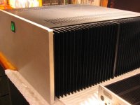
On a different note I spent the day installing the two 200VA transformers that arrived yesterday into the chassis. Switched on this afternoon and brought both channels up to about 270mA bias. Ran it for about two hours (heatsinks-MODU chassis 160mm high- only just warm) and set the dc offset then plugged in my old exposure cd player via a Creek passive pre-amp. A couple of old Sony speakers from a discarded music centre completed the picture. Even with these bog standard speakers perched on top of a shelf in the garage the sense of space and instrument positioning was very evident. Very happy and will post pictures sometime over the weekend.
As I listen to 'Kind of Blue' and wonder at how these humble electronic components produce such an amazing emotional response my thoughts turn to all of you who have helped over the years so thanks to you all and of course a special thanks to Nelson. I now have a BA-2 and a BA-3.
What about a BA-4?
As I listen to 'Kind of Blue' and wonder at how these humble electronic components produce such an amazing emotional response my thoughts turn to all of you who have helped over the years so thanks to you all and of course a special thanks to Nelson. I now have a BA-2 and a BA-3.
What about a BA-4?
6L6 I checked out the esp info...good stuff. I tried the dc blocker to no effect.
Backbones I'll add some info to the mix..
I swapped the other toroid I got from buzz into the amp and the mechanical noise dropped to almost nonexistent. Is it possible I got a bum transformer?
Backbones I'll add some info to the mix..
I swapped the other toroid I got from buzz into the amp and the mechanical noise dropped to almost nonexistent. Is it possible I got a bum transformer?
Quiz Time 
Your power supplies appear more complex than the Pass units. Can you give some details?
What are the large brown caps and why did you select them?
Are you using one bridge rectifier for both tranis? Just can't see a second.
Can't quite see where the speaker grounds are connected.
Yea, I'm nosy , but that's a nice clean set to gather some good ideas.
Your power supplies appear more complex than the Pass units. Can you give some details?
What are the large brown caps and why did you select them?
Are you using one bridge rectifier for both tranis? Just can't see a second.
Can't quite see where the speaker grounds are connected.
Yea, I'm nosy
, but that's a nice clean set to gather some good ideas. What are the large brown caps and why did you select them?
Are you using one bridge rectifier for both tranis? Just can't see a second.
Can't quite see where the speaker grounds are connected.
A quiz! Fun!
Elna Silmic
The bridges are discrete, on the PSU PCB, under clip-on heatsinks. The bridge on the back panel is a ground-breaker.
Back at the PSU
Backbones - a fantastic build! Thanks for sharing!
Last edited:
 Spelling bee is next ----
I'm a bit nosy myself when it comes to other people's designs.
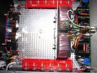
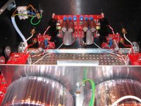
Power supplies are same as Nelson's design. I use boards from Avondale Audio over here in the UK. There is one each side. I have soldered a bank of 4 Schottky diodes (fitted with heatsinks) at one end which then feed into Nelson's CRC arrangement with a final 10uF 250V output cap made by Clarity. This gives the split rail supply so only one set of rectifying diodes per channel. The rest of the caps are 10,000uF Mundorfs. If you want the boards from Avondale unpopulated as I did you will have to phone them and in fact they may not do this size anymore but it is worth asking. They are mounted on the back of the front plate.
The large brown caps I think you are referring to are the 1000uF Elna Silmic II on the front ends. They don't quite fit the boards but they sound very good. They have an element of relaxed analogue about them without any loss of detail. Not sharp or brittle.
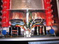
Speaker grounds are taken from the central pin on the power supply output boards (they are the white ones) and they pass to the upper speaker post. The other white ground is attached to the same output pin of the power supply and passes to the front end ground.
The central ground of the power supply is also connected to the earth ground via a CL60.
Power supplies are same as Nelson's design. I use boards from Avondale Audio over here in the UK. There is one each side. I have soldered a bank of 4 Schottky diodes (fitted with heatsinks) at one end which then feed into Nelson's CRC arrangement with a final 10uF 250V output cap made by Clarity. This gives the split rail supply so only one set of rectifying diodes per channel. The rest of the caps are 10,000uF Mundorfs. If you want the boards from Avondale unpopulated as I did you will have to phone them and in fact they may not do this size anymore but it is worth asking. They are mounted on the back of the front plate.
The large brown caps I think you are referring to are the 1000uF Elna Silmic II on the front ends. They don't quite fit the boards but they sound very good. They have an element of relaxed analogue about them without any loss of detail. Not sharp or brittle.
Speaker grounds are taken from the central pin on the power supply output boards (they are the white ones) and they pass to the upper speaker post. The other white ground is attached to the same output pin of the power supply and passes to the front end ground.
The central ground of the power supply is also connected to the earth ground via a CL60.
A quiz! Fun!
Elna Silmic CORRECT
The bridges are discrete, on the PSU PCB, under clip-on heatsinks. CORRECT
The bridge on the back panel is a ground-breaker. NO BRIDGE SORRY THAT IS WRONG
Back at the PSU
Backbones - a fantastic build! Thanks for sharing!
Itsa Pleasure
- Home
- Amplifiers
- Pass Labs
- Burning Amp BA-3