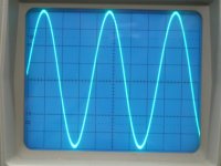
6000Hz sinewave
Hi, all
Here a 6KHz sinewave from the unfiltered octal D-I DAC, still no steps visible.
Something tubee posted made me think about exactly what makes a NOS-DAC sound so natural (oversampled DAC's often sound dull and not very natural). Despite it's squarewaved stepsignal it still sounds more natural than a DAC with oversampling. Mayby I am wrong, but I think it can't be the distortion alone we are discussing for a while now. There must be something we overlooked. When tubee posted that his NOS-DAC sounded more natural without the Bessel filter" it occured to me.
The main difference is filtering and the accompanied phase errors. When I was experimenting with active filters, I saw how critical the component values were. It's almost impossible to make two exactly identical (integrated) filters without using extremely low tolerance parts (0.1...0.01%), result: different phase response between L and R channel, blurred sound image.
Then there is the perception of sound by the human ear, it uses two signals to interpret sound around us. Minute phase delays tell a lot of how something sounds, and if it sounds natural or not. Research has shown that hearing high frequencies is limited, but slight phase differences can still be noticed. We use this ability to locate sound sources, and more important, to judge room acoustics (open air, cathedral, telephone booth and so on) and sound within them. Chesky audio has done some recordings with this in mind, and guess what, they sound beautiful on a NOS-DAC and rather dull on a DAC using oversampling (cannot recreate room acoustics properly?). So this is quite an important issue when reproducing a music recording, I think even more important then low distortion.
In a oversampling DAC or a DAC that uses filters, these filters differ due to component tolerances. So L and R channel react in a slightly different way.
In a NOS-DAC there is very little that can go wrong with the phase of L and R channel compared to a DAC using some kind of filtering.
Attachments
Re: 6000Hz sinewave
Same problem with speakers, crossovers.
And DAC chips because the two channels have a different distortion spectrum.
The worst are stereo DACs like the TDA1541.
Nearly impossible to find one where L & R match.
Paralleling might help
-ecdesigns- said:
In a oversampling DAC or a DAC that uses filters, these filters differ due to component tolerances. So L and R channel react in a slightly different way.
Same problem with speakers, crossovers.
And DAC chips because the two channels have a different distortion spectrum.
The worst are stereo DACs like the TDA1541.
Nearly impossible to find one where L & R match.
Paralleling might help
Octal D-I DAC prototype
Hi, poobah,
Ok, I just wanted to indicate you wouldn't get perfect squarewaves with very short risetimes, that's all. Good that you remind me, I could do some testing with squarewaves tomorrow and see how they look at different frequencies.
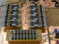
I added a photograph of the octal D-I DAC prototype, I assembled a second quad DAC PCB today.
Hi, poobah,
Ok, I just wanted to indicate you wouldn't get perfect squarewaves with very short risetimes, that's all
. Good that you remind me, I could do some testing with squarewaves tomorrow and see how they look at different frequencies.I added a photograph of the octal D-I DAC prototype, I assembled a second quad DAC PCB today.
Attachments
V8
Hi tubee,
thanks for your reply,
>Yes it looks a bit like a V8 engine, and it "runs" very smooth too . The output waveforms are soo smooth, you can't see any steps (see oscillograms), and that all without filtering! I also tested a 1KHz squarewave on the octal D-I dac (V8) and it looks fine (will post it later). Then I listened for quite some time yesterday. I think this is going to be my new reference DAC.
You were right about filtering, removing the filter makes the sound much more natural, but when you look at the FFT scan you can clearly see harmonics within the audio spectrum (post #119 that proves this), and that's only with one sinewave frequency!
The good news is that even with the unfiltered quad D-I DAC things look much better (post #121), and with the octal D-I DAC even more so (post #159)
Linear interpolation errors occur, but mainly at high frequencies, but it seems it gets worse without interpolation as can be seen on the FFT scans. So I think linear interpolation used in the D-I DAC is a good trade-off.
>All proto printed circuit boards are hand crafted. I use opaque sheets with a laserprinter to produce the film. Then I use the photographic process (UV) with photosensitive PCB's from Farnell. After developing, it is etched to remove the unwanted copper. Then I apply a thin coating of soldering tin to protect the PCB from oxidizing. After the holes are drilled, I use wires for the via's (boards are double sided but have no trough metallization) and solder all components on both sides (if necessary).
Sure I can make a few logic boards for people who want to try this setup. If the D-I DAC project is completed and enough people are interested, I could get some professional boards made.
I can also post some PDF files (layers 1,2 , silksheet and partlist), for those who want to make their own PCB's. But I have to convert them first.
Today I built a differential tube output stage (ECC83), for testing. It sounds fine, but I get a weak 50Hz humm and noise (I used regulated DC voltage for the filament and High voltage). Have to do some more testing with this.
With the OPA627 OP-ams (schematics I/V diagram, post #50 filterless diff amp) you can put your ear close to the speaker and wouldn't hear humm or noise. I replaced the 220 Omm resistors with 470 Ohm resistors (I/V) stage creating a output signal of around 7 volts for each I/V converter (octal D-I DAC), then I increased the resistor values of R3 and R4 to get the correct output voltage.
Hi tubee,
thanks for your reply,
>Yes it looks a bit like a V8 engine
, and it "runs" very smooth too . The output waveforms are soo smooth, you can't see any steps (see oscillograms), and that all without filtering! I also tested a 1KHz squarewave on the octal D-I dac (V8) and it looks fine (will post it later). Then I listened for quite some time yesterday. I think this is going to be my new reference DAC.You were right about filtering, removing the filter makes the sound much more natural, but when you look at the FFT scan you can clearly see harmonics within the audio spectrum (post #119 that proves this), and that's only with one sinewave frequency!
The good news is that even with the unfiltered quad D-I DAC things look much better (post #121), and with the octal D-I DAC even more so (post #159)
Linear interpolation errors occur, but mainly at high frequencies, but it seems it gets worse without interpolation as can be seen on the FFT scans. So I think linear interpolation used in the D-I DAC is a good trade-off.
>All proto printed circuit boards are hand crafted. I use opaque sheets with a laserprinter to produce the film. Then I use the photographic process (UV) with photosensitive PCB's from Farnell. After developing, it is etched to remove the unwanted copper. Then I apply a thin coating of soldering tin to protect the PCB from oxidizing. After the holes are drilled, I use wires for the via's (boards are double sided but have no trough metallization) and solder all components on both sides (if necessary).
Sure I can make a few logic boards for people who want to try this setup. If the D-I DAC project is completed and enough people are interested, I could get some professional boards made.
I can also post some PDF files (layers 1,2 , silksheet and partlist), for those who want to make their own PCB's. But I have to convert them first.
Today I built a differential tube output stage (ECC83), for testing. It sounds fine, but I get a weak 50Hz humm and noise (I used regulated DC voltage for the filament and High voltage). Have to do some more testing with this.
With the OPA627 OP-ams (schematics I/V diagram, post #50 filterless diff amp) you can put your ear close to the speaker and wouldn't hear humm or noise. I replaced the 220 Omm resistors with 470 Ohm resistors (I/V) stage creating a output signal of around 7 volts for each I/V converter (octal D-I DAC), then I increased the resistor values of R3 and R4 to get the correct output voltage.
Thanks Ecdesign for fast reaction
I am interested in a pdf of layout of logic (and of dac also) to make the PCB myself. Thanks in advance.
I made my first edged pcb for a kwak 7, including a clock divider chip on it, will show picture, i am at work now. My friend has a cd880, and want to try this pcb too. He made a AD627 I/V for PCM63 dac for Rotel RCD910 from his brother: sounds great with that chip. (and Guido Tent did some clock modifications on it too)
Nice you tried an tube stage, i have some ECC83 Haltron tubes lying arround here. I still want to finisch the 4 dac project, and tube output in my mind, with a leftover Sovtek 6922.
The humm could be from several causes, or a ground loop somewhere.
Re: V8
How well do you have to match the resistors? Also, have you tried other op amps, for example, AD8610?
Originally posted by -ecdesigns-
With the OPA627 OP-ams (schematics I/V diagram, post #50 filterless diff amp) you can put your ear close to the speaker and wouldn't hear humm or noise. I replaced the 220 Omm resistors with 470 Ohm resistors (I/V) stage creating a output signal of around 7 volts for each I/V converter (octal D-I DAC), then I increased the resistor values of R3 and R4 to get the correct output voltage. [/B]
How well do you have to match the resistors? Also, have you tried other op amps, for example, AD8610?
The D-I dac with eight 1541's is giving outstanding oscillograms. There exists a very small possibility that even Jocko Homo is following this thread. But this possiblity is very very small, he dislikes the 1541 and NON-OSsers in special. Well, Jocko, if you are following this, what is your opinion of the D-I dac?
Btw, with edged in earlier post i ment etched, i'm not an englischman, and to speak with Sting even not one in New York.
This was my first pcb product, kwak clock 7, designed the layout with TCI software. [img=http://img339.imageshack.us/img339/5862/kwak78ix.th.jpg]
Well, Jocko, if you are following this, what is your opinion of the D-I dac?Btw, with edged in earlier post i ment etched, i'm not an englischman, and to speak with Sting even not one in New York.
This was my first pcb product, kwak clock 7, designed the layout with TCI software. [img=http://img339.imageshack.us/img339/5862/kwak78ix.th.jpg]
tubee said:..........There exists a very small possibility that even Jocko Homo is following this thread. But this possiblity is very very small, ...............
He may well be following but cannot reply since he is currently BANNED !
Hi,
i am interested for PCBs.
I would go for octal D-I DAC, but i have to find another 4 TDA1541A, unless someone have for sale or know good source to buy them.
Which 14 capacitors do you use around TDA1541A?
I found in Farnell 0.1uF low inductance multilayer 0612 SMD capacitors.
Is OPA637 can be use here also?
regards, Bostjan
resistor tolerance
Hi, ezkcdude,
Thanks for your reply, I use 1% metal film resistors, but you can also use 0.1%.
its not critical. The properties of the I/V resistor however are important (very low inductance, low noise).
I did some experimenting with parallelling resistors to reduce inductivity (metal film resistors are laser tuned by creating a helical groove), this acts as a inductivity. So instead of 470 Ohm you could use 10 X 4K7 in parallel, in this case it is advisable to use 0.1% metal film resistors to maintain 1% overall tolerance. This technique works well in passive crossovers too. You can use 10X1W metal film resistors to make a 10W very low inductance metal film resistor. I think 4 resistors in parallel for each I/V stage is sufficient. Precision non-inductive metal foil resistors should work fine too, but they are very expensive, so I haven't tested them yet.. Precision wirewound resistors didn't work properly. When I opened one, it had 2 separate windings, one clockwise, and next to it, one counterclockwise...
OP-amps: yes I have tried other op-amps: OPA2604, AD823, AD825, OPA2132 and OPA627, I will try the AD8610 too, you never know.., thanks for the tip.
Hi, a333bt,
Thanks for your reply,
> PCB's: I could make some myself, or order professional PCB's later. There could be a modification on the QUAD-DAC board (DEM clock synchronizing).
I am also planning to make a main-board for these modules.
> Capacitors, I use 2222 470 series (BC components) capacitors for decoupling (grey colored cap's on the photo) 100nF has Farnell part number 567-450. I used small capacitors for optimal decoupling (very short tracks) larger cap's would make this very difficult. They should be foil types, if you can give me the partnumber of the SMD cap, I can check this for you.
> OPA627 is unity gain stable (internally compensated), OPA637 is stable at gains greater than 5. Since the diff amp is unity gain, you must use a OPA627 to avoid oscillations. Same would apply for the I/V stages, using OPA637 here could result in oscillations as well.
Hi,
thank you for reply.
i found these SMD capacitors are X7R and to big. You can check in Farnell: 335-1816.
Maybe is interested page this:
http://www.icst.com/appnotes/loopfilter.pdf
I will order same capacitors as you have, to make life easier. They are good enough.
Are resistors Welwyn RC55 0.25W, 0.1%, 15ppm good choice?
Farnell: 339-672 (3k3)
Usually i use Vishay-dale RD60D resistors, cheap and good.
I will wait for PCBs.
DEM would be nice, i have good experiences with it.
regards, Bostjan
Ecdesigns, i agree too to add dem reclock on dac pcb.
Thanks for the extra work.
Btw, the pcb's are doublesided, what will be the price of them when you make a few for us? I never made doubled ones.
When more diyers are interested, the professionally fabricated ones, what would they cost?
Thanks for the extra work.
Btw, the pcb's are doublesided, what will be the price of them when you make a few for us? I never made doubled ones.
When more diyers are interested, the professionally fabricated ones, what would they cost?
Hi ecdesigns,
It seems like many of us, including myself, are willing to pay for a professionally made PCB. Since you are calling it "the ultimate NOS DAC", why not get the best made PCB we can get. Double sided, 4 layer board? BTW, I've seen some highend companies use teflon PCB boards with silver traces - wonder how much these would cost? $100 USD? As long as the PCB is designed to get the best performance from these chips, I'm willing to pay for the extra cost. I love this thread!
It seems like many of us, including myself, are willing to pay for a professionally made PCB. Since you are calling it "the ultimate NOS DAC", why not get the best made PCB we can get. Double sided, 4 layer board? BTW, I've seen some highend companies use teflon PCB boards with silver traces - wonder how much these would cost? $100 USD? As long as the PCB is designed to get the best performance from these chips, I'm willing to pay for the extra cost. I love this thread!
resistors / capacitors
Hi, a333bt
Thanks for your reply,
> The X7R caps's are not suitable to replace the 14 decoupling cap's since they are ceramic types.
> I used the RC55 welwyn resistors, I build a twin DAC years ago with all MRS25 replaced by RC55 resistors. Listening sessions showed that it sounded less natural, so I had to replace them with the MRS25 again.
The MRS25 series are fine for 1% tolerance. I also had good experiences with the new YR1 series (0.1%) note that the Farnell catalogue indicates 1% (this is an error). The YR1 is ideal for parallelling resistors in the I/V stage.
Hi, a333bt
Thanks for your reply,
> The X7R caps's are not suitable to replace the 14 decoupling cap's since they are ceramic types.
> I used the RC55 welwyn resistors, I build a twin DAC years ago with all MRS25 replaced by RC55 resistors. Listening sessions showed that it sounded less natural, so I had to replace them with the MRS25 again
.The MRS25 series are fine for 1% tolerance. I also had good experiences with the new YR1 series (0.1%) note that the Farnell catalogue indicates 1% (this is an error). The YR1 is ideal for parallelling resistors in the I/V stage.
Hi tubee
Thanks for your reply [post#174]
>If I make the circuit boards myself they would be more expensive than professional ones, as it takes several hours to make them. But I have a look what I can do.
>The price of professional ones depends upon the amount of circuit boards and materials used. You can have plain PCB's with a standard green anti-solder mask or more professional ones with gold plated tracks and a blue anti-solder mask.
>Basically you can make double sided ones by taping two films together and slide a double sided photosensitive board in between, then fixate the PCB with some tape on each side. Then apply the same process for both sides. Perhaps I could start a thread later on, that describes in to detail how to make circuit boards yourself.
Hi, MGH
thanks for your reply [post#175]
> I agree, the D-I dac deserves professional circuit boards, and professional PCB's would make it much easier to assemble and reduces the chance of short circuits.
> Since all modules have simple straight forward routing and use no fine pitch SMD components, I don't see the necesity of using multilayer boards. As for ground planes, this task will be solved by the main board that has a large ground plane, so when the modules are placed on this main board you have a similar situation as 4 layer board.
> I am thinking of PCB's with gold plated tracks, I have seen some examples and the price would't be much higher than tin plated tracks. Silver has only slightly better conductance than copper. One could also increase the thickness of the tracks, effectively decreasing track resistance even more.
> More important is to keep interference and cross-talk as low as possible, this is mainly done by design. I used separate Digital and Analog ground planes. I try to screen the digital signals (BCK, WS and DATA), so they don't interfere with the analog signal. Separate power supply regulators for each individual module reduces interference as well.
Thanks ecdesigns.
I would love to have a PCB with silver or thicker copper tracks with gold plating. That would look so professional - Threshold (Nelson Pass's era) preamps had beautiful gold plated tracks and lasted forever. I like the idea of silver tracks on PCBs because I like to use silver wires on the analogue side, but on the digital side I guess it wouldn't matter much.
I really like your idea of placing the modules on the main board that has a large ground plane, effectively acting like a 4 layer board in some respects. But the question is, will you go for the standard glass epoxy or Teflon PCB board? I don't know how hard Teflon PCBs are to find, but they are much more stable over time and temperature compared to glass epoxy. I don't know how much heat 8 TDA1541s and all those other chips generate, but you could tell us.
I completely agree with you that the most important aspect of PCB design is the design itself - keeping cross talk to a minimum, keeping the analogue and digital ground planes separate, and using separate power supply regulators for each module.
Have you thought about batter power or USB interface?
With your innovative approach to NOS DAC and the above PCB design, I think you will come up with a DAC that deserves the "ultimate" designation.
- Home
- Source & Line
- Digital Line Level
- Building the ultimate NOS DAC using TDA1541A