D-I DAC completion
Hi MGH,
Thanks for your reply [post #1216]
As for the D-I DAC design, the D-I 8 is ready (I/V diff amp module is now modified to accept the LM4562 without adapter socket), the D-I 16 is ready (D-I 16 core is modified to accept 3 X LM4562 without adapter socket). Some delays were introduced by testing and adapting the D-I DACs to the new LM4562 OP-amp, and reducing jitter, but regarding the improvements made, it was worth it.
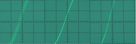
The added photograph shows what I have been doing lately, the timebase setting equals 5ns/div.
The oscillogram on the left is the BCK output from the PCM2706 chip (USB interface) with extensively filtered power supply and clocked with a low jitter 12 MHz clock, the hazy transient is caused by jitter, lots of it, approx. 1000ps.
The oscillogram in the center shows the optimized shiftregister reclocker output, a razor sharp transient with approx. 10ps jitter, due to the very low jitter, it also appears brighter, that's more like it.
The oscillogram on the right shows a direct I2S output from a Philips transport, when you look closely, it contains more jitter than the shiftregister reclocker output, the transient is a bit hazy and less bright.
I think this was worth investing some extra time, lowering jitter to these extreme low values does wonders to the sound quality of the D-I DACs. Comparing both optimized D-I 8 and D-I 16 with the reference octal D-I DAC with the OPA627 showed how much improvement still could be made.
> It's not a never ending process, the last modifications (LM4562 and reducing jitter) had such a impact on sound quality that I am now finally satisfied with it. If everything goes as planned, all D-I 8 and D-I 16 PCBs will be ordered this month. I will try to add the universal I2S interface PCB too.
Hi MGH,
Thanks for your reply [post #1216]
As for the D-I DAC design, the D-I 8 is ready (I/V diff amp module is now modified to accept the LM4562 without adapter socket), the D-I 16 is ready (D-I 16 core is modified to accept 3 X LM4562 without adapter socket). Some delays were introduced by testing and adapting the D-I DACs to the new LM4562 OP-amp, and reducing jitter, but regarding the improvements made, it was worth it.
The added photograph shows what I have been doing lately, the timebase setting equals 5ns/div.
The oscillogram on the left is the BCK output from the PCM2706 chip (USB interface) with extensively filtered power supply and clocked with a low jitter 12 MHz clock, the hazy transient is caused by jitter, lots of it, approx. 1000ps.
The oscillogram in the center shows the optimized shiftregister reclocker output, a razor sharp transient with approx. 10ps jitter, due to the very low jitter, it also appears brighter, that's more like it.
The oscillogram on the right shows a direct I2S output from a Philips transport, when you look closely, it contains more jitter than the shiftregister reclocker output, the transient is a bit hazy and less bright.
I think this was worth investing some extra time, lowering jitter to these extreme low values does wonders to the sound quality of the D-I DACs. Comparing both optimized D-I 8 and D-I 16 with the reference octal D-I DAC with the OPA627 showed how much improvement still could be made.
> It's not a never ending process, the last modifications (LM4562 and reducing jitter) had such a impact on sound quality that I am now finally satisfied with it. If everything goes as planned, all D-I 8 and D-I 16 PCBs will be ordered this month. I will try to add the universal I2S interface PCB too.
Attachments
") .
.Hi a333bt,
Thanks for your reply [post#1222]
Yes the LM4562 sounds much clearer than the OPA627 I used before, it works very well with the D-I system.
Yes, both D-I DACs can be used with ubuntu, I already tested the Rhythmbox Music player and the Banshee Music Player. Both work fine. Make sure you use the FLAC audio format (lossless compression).
The PCM2706, used in the USB/DI2S interface is compatible with both USB1.1 and USB2, maximum sample rate is 48 KHz. No drivers are needed.
Unlike many other USB audio interfaces, the USB/DI2S module's shiftregister reclocker and the low jitter design enable direct I2S performance.
Thanks John. I can't wait. Would you be willing to offer D-I 8 partially assembled? I mean having all the chip sockets, resistors, capacitors, diodes etc already soldered onto the PCB. We can add the final touches like installing the chips (you won't have to provide the chips), screwing the PCBs into the housing, connecting the RCA jacks, LED indicators on the front, etc. I know this would drive up the cost of the kit because of more work on your part, but some of us may opt for it if offered. It's better to have the MASTER do the critical assembly than have us novice screw things up. Just a thought.
Regards.
Regards.
Would you be willing to offer D-I 8 partially assembled?
Best way to build boards is starting with resistors, then the caps and finally the chips, ESD safety. Chips in sockets ease it up too.
D-I DAC PCB's
Hi MGH,
Thanks for your reply [post #1224]
Yes, of course it's possible to obtain (partially) assembled PCB's. I was already planning to assemble the "difficult" SMD parts like the PCM2706 and the UHS buffers. The D-I DACs will be available ranging from PCB's only to completely assembled and tested.
Building the D-I DAC is not as difficult as it looks, however, some basic (soldering) skills are required of course. It's also important to take your time during assembly and double-check everything. Due to the modular design, and the use of IC sockets, functional tests can be carried out to locate errors before they could cause any damage.
I am planning to provide a CD containing detailed step by step assembly and test instructions with lots of photographs. The CD will also contain partlists with order codes, and a lot of extra information about the D-I DAC.
Hi John, that's great news! I already have the TDA1541 chips, so I may consider getting your D-I 8 DAC almost completely assembled, minus the TDA1541 chips of course. Or I guess I can ship the TDA1541 chips to you so you can install and test them.
BTW, what kind of solder do you use? I'm trying to stay away from lead solder, if possible. I hear lead free solders with silver are good alternatives.
BTW, what kind of solder do you use? I'm trying to stay away from lead solder, if possible. I hear lead free solders with silver are good alternatives.
D-I-8-dac
Dear John,
D-I-Octal dac
----------------
First best wishes for 2007
Nice to see that everything is almost ready.
I am curious to see a list what is possible.
Units, PCB's, assembled or not, parts etc.
I guess that a lot of people here are waiting for such a list too.
Regards,
Onno
Dear John,
D-I-Octal dac
----------------
First best wishes for 2007
Nice to see that everything is almost ready.
I am curious to see a list what is possible.
Units, PCB's, assembled or not, parts etc.
I guess that a lot of people here are waiting for such a list too.
Regards,
Onno
Would this be a good time to mention I have 100-pcs of TDA1543 in stock, purchased from a local distributor with a 100-pcs minimum order quantity? I'd be happy to sell the ~80-pcs I don't plan on using to other DIY-ers, just PM me for details.
Best regards,
Sander Sassen
http://www.hardwareanalysis.com
Best regards,
Sander Sassen
http://www.hardwareanalysis.com
Lead-free solder issues
Hi MGH,
Thanks for your reply [post #1227]
If it was my D-I DAC, I wouldn't even consider using lead free solder for a millisecond. If you like to enjoy your D-I DAC for more than a few months, use leaded solder that has proven it's reliability for decades.
Searching the internet about the problems introduced by lead-free solder can be very revealing.
I used leaded solder with 1% silver added for my D-I DACs.

I informed also in lead free solder at my parts-providing shop. It's available, but for a good soldering joint they advised not to use lead free because of more brittle solder joints.
The 2% silver solder i often use for the analog part of schematics.
And its very important too imo that the holes in the pcb with classic through hole parts mounting is just big enough for the pin, and not having a huge hole. It's a long way then for the current to go along the relatively bad conducting solder joint, even with 2% silver.
DI DAC configurations / parts
Hi Onnosr,
Thanks for your reply [post #1228]
I am planning to provide an electronic order form (on my website) that calculates prices real-time as items are added / removed. It also allows for customizing your D-I DAC. When ready, the form can be submitted.
Ok, I made a list of what I am planning to provide, just to give a quick impression of what's possible.
D-I 8 (DI 8 OP-amp output only)
1 DI 8 mainboard, PCB only, PCB assembled, kit
8 DI 8 D/A board, PCB only, PCB with only SMD parts assembled, PCB assembled (without TDA1541A), kit (without TDA1541A)
2 DI 8 I/V diff board, PCB only, PCB with assembled SMD parts only, PCB assembled, kit
1 DI 8 Timing board, PCB + PAL only, PCB + PAL + assembled SMD parts only, PCB assembled, kit
1 DI 8 Main PS board, PCB only, PCB assembled, kit
1 DI 8 Attenuator board, PCB only, PCB assembled, kit
1 USB/DI2S board, PCB only, PCB with assembled SMD parts only, PCB assembled, kit
- DI 8 cable assemblies + connectors + LED optics
- DI 8 housing (all parts available separatel), large housing
- DI 8 heatsink assembly (parts available separately)
- DI 8 complete product assembled and tested, kit
D-I 8M (DI 8 Mixed mode)
1 DI 8 mainboard, PCB only, PCB assembled, kit
8 DI 8 D/A board, PCB only, PCB with only SMD parts assembled, PCB assembled (without TDA1541A), kit (without TDA1541A)
2 DI 8 I/V diff board, PCB only, PCB with assembled SMD parts only, PCB assembled, kit
1 DI 8 Timing board, PCB + PAL only, PCB + PAL + assembled SMD parts only, PCB assembled, kit
1 DI 8 Main PS board, PCB only, PCB assembled, kit
1 DI 8 Tube PS board, PCB only, PCB assembled, kit
2 DI 8 Tube diff amp board, PCB only, PCB assembled, kit
1 DI 8 Attenuator board, PCB only, PCB assembled, kit
1 USB/DI2S board, PCB only, PCB with assembled SMD parts only, PCB assembled, kit
- DI 8M cable assemblies + connectors + LED optics
- DI 8M housing (all parts available separately), large housing with tube protection grille
- DI 8 heatsink assembly (parts available separately)
- DI 8M complete product assembled and tested, kit
D-I 16
1 DI 16 core, PCB + PAL only, PCB with only assembled SMD parts, PCB assembled, kit
1 DI 16 PS, PCB only, PCB assembled, kit
1 USB/DI2S board, PCB only, PCB with assembled SMD parts only, PCB assembled, kit
- DI 16 cable assemblies + connectors
- DI 16 housing (all parts available separately), small housing
- DI 16 heatsinks
- DI 16 complete product assembled and tested, kit
D-I 16M (DI 16 Mixed mode)
1 DI 16 core, PCB + PAL only, PCB with only assembled SMD parts, PCB assembled, kit
1 DI 8 Main PS board, PCB only, PCB assembled, kit
1 DI 8 Tube PS board, PCB only, PCB assembled, kit
2 DI 8 Tube diff amp board, PCB only, PCB assembled, kit
1 DI 8 Attenuator board, PCB only, PCB assembled, kit
1 USB/DI2S board, PCB only, PCB with assembled SMD parts only, PCB assembled, kit
- DI 16M cable assemblies + connectors + LED optics
- DI 16M housing (all parts available separately), large housing with tube protection grille
- DI 16 heatsinks
- DI 16M complete product assembled and tested, kit
INTERFACE
- Universal I2S interface, PCB only, PCB with assembled SMD parts only, PCB assembled, kit
This interface basically takes a (jittery) SPDIF coax / optical or I2S philips format 64BCK and converts it to DI2S used by the DI DACs. A reclocker circuit (Synchronous reclocker or Shiftregister reclocker) provide direct I2S performance, regardless of the source. When using a SPDIF source, the input format is automatically converted to the desired 64BCK Philips format. This way CD transports that do not support the 64BCK Philips format like the CDPRO2 can still be connected trough the DOBM (SPDIF) output, by using synchronous reclocking with a low jitter master clock, direct I2S performance is guaranteed.
MISCELANEOUS
IC adapter sockets + heatsink (to experiment with different OP-amps)
Low jitter master clock module (to improve jitter performance of existing transport master clock)
DI2S interlinks, stranded wire / twisted pair
DI2S connectors (DIN 6 way)
Both the DI 8 and DI 16 core can run in balanced mode (default) or in single-ended mode to allow for experimenting with different I/V and output circuitry.
Regards,
John
Re: DI DAC configurations / parts
John (EC),
Are you using a PLL/VCXO to reclock I2S and SPDIF clocks?
cheers
Terry
-ecdesigns- said:Hi Onnosr,
INTERFACE
- Universal I2S interface, PCB only, PCB with assembled SMD parts only, PCB assembled, kit
This interface basically takes a (jittery) SPDIF coax / optical or I2S philips format 64BCK and converts it to DI2S used by the DI DACs. A reclocker circuit (Synchronous reclocker or Shiftregister reclocker) provide direct I2S performance, regardless of the source. When using a SPDIF source, the input format is automatically converted to the desired 64BCK Philips format. This way CD transports that do not support the 64BCK Philips format like the CDPRO2 can still be connected trough the DOBM (SPDIF) output, by using synchronous reclocking with a low jitter master clock, direct I2S performance is guaranteed.
John
John (EC),
Are you using a PLL/VCXO to reclock I2S and SPDIF clocks?
cheers
Terry
I have not been following this interesting thread all the time and I am somewhat confused now as to the to the differences between two different dacs and options available and how they affect sound etc.
Also the pages in this thread on this innovative design and subsequent modifications are many.
I was wondering if ec designs would be so kind as to provide a technical ´´manual´´ of his design so it may be easier for all of us to study?
Also the pages in this thread on this innovative design and subsequent modifications are many.
I was wondering if ec designs would be so kind as to provide a technical ´´manual´´ of his design so it may be easier for all of us to study?
Reclocking / reducing jitter
Hi Terry Demol,
thanks for your reply [post#1238]
No I don't use PLLs as they still pass the jitter trough to some extent. When the input signal contains a lot of jitter (long interlinks), the PLL can't get a perfect lock and could make matters even worse. A PLL has to lock-in to the received clock signal, and in order to do so, it has to vary it's phase continuously to some extent. That's just what I try to avoid. The PLL circuitry itself also adds phase noise, phase noise is closely related to jitter.
I don't use VCXO (voltage controlled crystal oscillators) because of the very limited locking range. This could cause periodic lock-outs due to tolerances between the clock source and the VCXO causing clicks and pops. The circuitry used to vary the XO clock frequency could also add jitter / phase noise. Another problem is that you will need a separate VCXO for each sample frequency used.
I use either a shiftregister reclocker (combined synchronous digital one-shot + reclocker + specific crystal frequency) or a synchronous reclocker (based on synchronous shiftregisters). A synchronous reclocker can only be used if a master clock is available that runs in sync with the generated digital bitstream (CD transport). SPDIF signals are first converted to I2S (Philips format), then the clock output of the audio receiver is reclocked synchronously (this needs some modding). When there is no master clock available, only a standard SPDIF output, the shiftregister reclocker is used.
Both reclockers have a wide locking range and low jitter / phase noise. They will accept different sampling rates and allow switching between various digital audio sources.
Both reclockers run fully synchronous with the reclock timing source used (master clock from a CD transport or a separate crystal clock). Obtaining and maintaining low jitter is extremely difficult, one single inverter or buffer can increase jitter easily up to 100ps or more. One must tune the design accurately to get a low jitter clock at the DAC chips. Feeding both BCK and data signals to one chip causes crosstalk / phase noise, always use a separate chip for BCK. Same applies for a LSI that outputs both BCK and DATA (direct I2S output from a CD transport), there will be crosstalk. All wires transporting clock / data signals need to be screened.
Once crosstalk is present and the circuitry can't be modified (LSI), the clock signal needs to be synchronously reclocked (with a separate IC).
I also had to tune the clock buffer trigger window and loading to obtain lowest jitter values, then there is the digital power supply. I now filtered the power supply for every single chip separately (short HF paths) in the BCK circuitry. Turned out it's a bad idea to directly connect the VCC / VDD pins together as this dumps the sum of HF energy produced by all chips connected to the digital power supply (long HF paths), decoupling caps won't help much here, even a low noise power supply will be useless now.
cheers,
John
- Home
- Source & Line
- Digital Line Level
- Building the ultimate NOS DAC using TDA1541A