More DEM confusion
Hi John, All,
I've been looking again at your DEM circuit, and I confused that you use BCLK and divide that down for the DEM clock.
HtP uses 256Fs (11.2Mhz).
I've seen other threads where 8Fs and 6Fs are quoted.
What should be used for NOS, and what reasoning is there behind this/these choice/s?
Cheers,
Phil
Hi MGH,
Thanks for your reply [post#960]
Well the end of the tunnel could be very close. If everything goes as planned, the octal D-I DAC prototype could be ready at the end of this week.
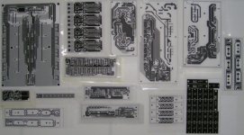
I also contacted my printed circuit board manufacturer. The printed circuit boards are epoxy types with thick copper gold plated traces, a transparent solder mask, and silkscreen is printed in black.
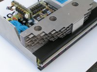
I have added a photograph of all plots of the completed DAC PCB's, to give some idea of the effort involved. All layouts were manually routed and some of them have been redesigned several times.
I will now give a overview of all printed circuit boards used in the octal D-I DAC prototype:
CONTROLS / INDICATORS:
2 X Keyboard PCB (160 X 24mm) single-sided
2 X Backlit Key PCB (152 X 24mm) single sided
1 X Backlit Logo PCB (96 X 16mm) single sided
1 X System controller (160 X 35mm) double sided
1 X Key icon PCB (80 x 63mm) single sided 0.5mm thick
OCTAL D-I DAC CORE:
1 X Analog mainboard (242 X 172mm) double sided
1 X Timing-chain module (146 X 55mm) double sided
8 X TDA1541A module (100 X 35mm) double sided
2 X I/V and diff amp module (81 X 30mm) double sided
2 X OPA627 converter (10 X 10mm) double sided
1 X UHS buffer / inverter (20 X 10mm double sided)
TUBE AMPLIFIER
2 X Tube diff amp module (160 X 74mm) double sided
1 X Tube amplifier power supply module (192 X 110mm) double sided
POWER SUPPLY
1 X Main power supply module (240 X 110mm) double sided
INTERFACE
1 X I2S input selector module (to be designed)
1 X USB to I2S interface module (128 X 35mm)
OUTPUT
1 X Analog mode switch (to be designed)
In addittion to the basic DAC setup, optional modules will be designed as well like SPDIF interfaces, universal I2S interface module
There will also be optional modules like a reclocked SPDIF interface module, universal I2S interface module and a differential I2S receiver.
As noted before, modules can also be used separately.
Thanks for your reply [post#960]
Well the end of the tunnel could be very close. If everything goes as planned, the octal D-I DAC prototype could be ready at the end of this week.
I also contacted my printed circuit board manufacturer. The printed circuit boards are epoxy types with thick copper gold plated traces, a transparent solder mask, and silkscreen is printed in black.
I have added a photograph of all plots of the completed DAC PCB's, to give some idea of the effort involved. All layouts were manually routed and some of them have been redesigned several times.
I will now give a overview of all printed circuit boards used in the octal D-I DAC prototype:
CONTROLS / INDICATORS:
2 X Keyboard PCB (160 X 24mm) single-sided
2 X Backlit Key PCB (152 X 24mm) single sided
1 X Backlit Logo PCB (96 X 16mm) single sided
1 X System controller (160 X 35mm) double sided
1 X Key icon PCB (80 x 63mm) single sided 0.5mm thick
OCTAL D-I DAC CORE:
1 X Analog mainboard (242 X 172mm) double sided
1 X Timing-chain module (146 X 55mm) double sided
8 X TDA1541A module (100 X 35mm) double sided
2 X I/V and diff amp module (81 X 30mm) double sided
2 X OPA627 converter (10 X 10mm) double sided
1 X UHS buffer / inverter (20 X 10mm double sided)
TUBE AMPLIFIER
2 X Tube diff amp module (160 X 74mm) double sided
1 X Tube amplifier power supply module (192 X 110mm) double sided
POWER SUPPLY
1 X Main power supply module (240 X 110mm) double sided
INTERFACE
1 X I2S input selector module (to be designed)
1 X USB to I2S interface module (128 X 35mm)
OUTPUT
1 X Analog mode switch (to be designed)
In addittion to the basic DAC setup, optional modules will be designed as well like SPDIF interfaces, universal I2S interface module
There will also be optional modules like a reclocked SPDIF interface module, universal I2S interface module and a differential I2S receiver.
As noted before, modules can also be used separately.
Attachments
DEM clock frequency
Hi philpoole,
Thanks for your reply [post#962]
The DEM clock frequency for the TDA1541A is specified at 150...250 KHz. So I divided BCK (2.8224 MHz) by 16 using a synchronous counter. Frequency is now 176.4 KHz, it's in sync with BCK and it is within specified Dynamic Element Matching clock frequency range. When using a 470pF capacitor connected to the TDA1541A's DEM clock oscillator, it will run at approx. 200KHz.
Cheers,
John
Hi Tube-Guy,
Thanks for your reply [post#961]
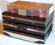
Yes development of the octal D-I DAC has taken a long time, but now it's almost ready. I have to start thinking about the colours to use for the external of the housing as I have to get it annodized soon. I made some photographs of the complete set, perhaps I should use a two colour housing. Lower part black like my existing set and the upper part gold coloured. I added a photograph of the complete set.
Thanks for your reply [post#961]
Yes development of the octal D-I DAC has taken a long time, but now it's almost ready. I have to start thinking about the colours to use for the external of the housing as I have to get it annodized soon. I made some photographs of the complete set, perhaps I should use a two colour housing. Lower part black like my existing set and the upper part gold coloured. I added a photograph of the complete set.
Attachments
Hi Ecdesigns,
Epic.
Do you plan a TDA1543 PCB? Octal or else...
Best.
M
I have added a photograph of all plots of the completed DAC PCB's, to give some idea of the effort involved.
Epic.
Do you plan a TDA1543 PCB? Octal or else...
Best.
M
-ecdesigns- said:Hi Tube-Guy,
Thanks for your reply [post#961]
Yes development of the octal D-I DAC has taken a long time, but now it's almost ready. I have to start thinking about the colours to use for the external of the housing as I have to get it annodized soon. I made some photographs of the complete set, perhaps I should use a two colour housing. Lower part black like my existing set and the upper part gold coloured. I added a photograph of the complete set.
I can't vouch for the sound quality, of course, but your craftsmanship is certainly exceptional. Bravo.
-ecdesigns- said:Hi Tube-Guy,
Thanks for your reply [post#961]
Yes development of the octal D-I DAC has taken a long time, but now it's almost ready. I have to start thinking about the colours to use for the external of the housing as I have to get it annodized soon. I made some photographs of the complete set, perhaps I should use a two colour housing. Lower part black like my existing set and the upper part gold coloured. I added a photograph of the complete set.
Hi John,
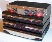
colour like this? Just idea.
regards, Bostjan
Attachments
I2S input switch module completed
Hi a333bt,
Thanks for your suggestion [post#968]
Yes I like the coulours you suggested, it combines good with the rest of the set. If the top part is annodized aluminum or gold colour, it just looks as if it's not part of the DAC.
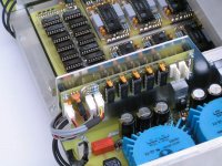
The differential I2S input switch module is ready too. I mounted it opposite to the USB to I2S interface, a PCB connector was used to connect the USB interface outputs to I2S input 3. I added a photograph showing the I2S input switch module and the modified chassis part that holds both modules.
Hi a333bt,
Thanks for your suggestion [post#968]
Yes I like the coulours you suggested, it combines good with the rest of the set. If the top part is annodized aluminum or gold colour, it just looks as if it's not part of the DAC.
The differential I2S input switch module is ready too. I mounted it opposite to the USB to I2S interface, a PCB connector was used to connect the USB interface outputs to I2S input 3. I added a photograph showing the I2S input switch module and the modified chassis part that holds both modules.
Attachments
I get water in my mouth when i see those nice PCB's and parts. Logical placement of parts too. What lytics you used in PS John, Panasonics?
I use wooden side panels too, 3rd time now for the diy casework of cdp. Nice looks with brushed alu front plate.
(off topic: just bought a new CD from audioslave, in the shop they had a Onkyo cdp and Sennheiser phones. At this moment i listen to the same CD with modded 304mk2 and diy tube headphone-amp and AKG phones. What a huge difference in sound! I am sure they will sell a lot more CD's when they replay music with this gear )
)
btw nice avatar Ec
I use wooden side panels too, 3rd time now for the diy casework of cdp. Nice looks with brushed alu front plate.
(off topic: just bought a new CD from audioslave, in the shop they had a Onkyo cdp and Sennheiser phones. At this moment i listen to the same CD with modded 304mk2 and diy tube headphone-amp and AKG phones. What a huge difference in sound! I am sure they will sell a lot more CD's when they replay music with this gear
)btw nice avatar Ec
A german magazine "Audio" recommended this album as "klangtipp" so was curious about it. But i do not allways agree with those Klangtipps.
Nowadays a lot of music is compressed, and Audioslave is from Sony BMG, not the best studio imo. This music especially is compressed to get it within the 16 bit limit. (but Limp Biscuit-Behind blue eyes doesn't suffer from this though)
Nowadays a lot of music is compressed, and Audioslave is from Sony BMG, not the best studio imo. This music especially is compressed to get it within the 16 bit limit. (but Limp Biscuit-Behind blue eyes doesn't suffer from this though)
 , and only hear a humm. I/V problem i think (with AD844)
Hi maxlorenz,
Thanks for your reply [post#966]
Yes I am still planning to design a single board TDA1543 based D-I DAC with 8...64 X TDA1543.
[post#972]
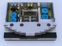
Wooden side panels for the DAC are no problem as the aluminum side panels mounted are chassis supports only, the wooden panels can be mounted on top of these aluminum side panels. I added a photograph to illustrate this.
Thanks for your reply [post#966]
Yes I am still planning to design a single board TDA1543 based D-I DAC with 8...64 X TDA1543.
[post#972]
Wooden side panels for the DAC are no problem as the aluminum side panels mounted are chassis supports only, the wooden panels can be mounted on top of these aluminum side panels. I added a photograph to illustrate this.
Attachments
Hi all,
Project update,
The octal D-I DAC's final printed circuit board, the analog mode switch module has been completed. It allows switching between op-amp, tube and mixed mode at the touch of a button. The actual switching is done by reed relays that re-arrange the attenuator resistors. The module is mounted on the rear panel, close to the RCA sockets.
The following connections are located on the rear panel:
1 X Mains connection
2 X I2S connector (large 6-way DIN connector)
1 X USB-B connector
2 X RCA sockets for analog L + R outputs
2 X RCA sockets for audio bus (used for remote control of the DAC)
I added a photograph of the analog mode switch, it is mounted on the aluminum rear panel. I added ventilation slots at the top of the rear panel, the air-intake will be located at the bottom plate close to the front of the octal D-I DAC. This way the cool air flows trough the entire DAC housing and exits at the rear.
Attachments
Hi all,
Project update,
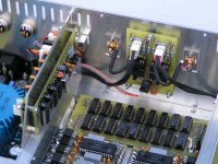
I added another photograph of the octal D-I DAC with all modules mounted. The rear panel is ready too. The two DIN connectors on the left are the differential I2S inputs (I need to add the wiring). The main power supply is on the left, above it is the differential I2S input switch that toggles between 3 inputs, USB inclusive. Opposite to the differential I2S input switch is the USB interface. In the center is the analog mainboard, with I/V diff amps, AD's and autodetecting timing chain. The analog mode switch is on the rear panel, with the L and R connections right beside it. On the right is the tube power supply. Above it are the two connections for the audio bus, it is used for remote control. At the front is the grille with the two tube amplifier modules. Behind the front cover are the switches, backlighting and the system controller.
So basically the octal D-I DAC is almost ready.
Project update,
I added another photograph of the octal D-I DAC with all modules mounted. The rear panel is ready too. The two DIN connectors on the left are the differential I2S inputs (I need to add the wiring). The main power supply is on the left, above it is the differential I2S input switch that toggles between 3 inputs, USB inclusive. Opposite to the differential I2S input switch is the USB interface. In the center is the analog mainboard, with I/V diff amps, AD's and autodetecting timing chain. The analog mode switch is on the rear panel, with the L and R connections right beside it. On the right is the tube power supply. Above it are the two connections for the audio bus, it is used for remote control. At the front is the grille with the two tube amplifier modules. Behind the front cover are the switches, backlighting and the system controller.
So basically the octal D-I DAC is almost ready.
Attachments
- Home
- Source & Line
- Digital Line Level
- Building the ultimate NOS DAC using TDA1541A