Yup 6126 is what 7057 was based on, but it had a bit issues which required users to modify it, so he made one with a moved latch enable window in 7092, then @xaled made an interface board using it, that's how i understand it at least.
But you raise a fair point rfbrw still because very few users even played with this, and @koldby was using a modified version of the old schematic. Xaled did you ever test your board by any chance? Because now that i think of it im not sure i saw people using 7092, since the thread started waning around this time...
But you raise a fair point rfbrw still because very few users even played with this, and @koldby was using a modified version of the old schematic. Xaled did you ever test your board by any chance? Because now that i think of it im not sure i saw people using 7092, since the thread started waning around this time...
Okay, i managed to do both in simultaneous mode (according to JLsounds documentation), and even paralell them from twice the current, then trim to 0V DC with the ground lift potentiometer.
I guess it technically "works", but there is a terrible crackling noise. At first i thought i just needed to wait for the DEM caps to charge but nothing changes even after 20mins. I wiggled all the caps and everything on the board, just in case. I disconnected one TDA1541, and then the other, and basically it's identical in both so its not them (or they're somehow broken in identical ways). Maybe its just because i have non-A version, and 50Hz reclock doesnt work with it.
I think...the I/V (from previous page) should be ok, TDA1541 should be ok, so its maybe only the JLsounds to blame?
When i look at the RMS voltage of the lines on the multimeter:
LEO/WS = 10mv AC, 50mv DC
BCKO = 0mv (freq too high for DMM to read probably), 850mv DC
Data R (pin 3) = 65mv AC, 620mv DC
Data L (pin 4) = 5mv AC, 820mv DC
First no clue why one data channel is higher voltage than the other, but measuring this with the multimeter is kind of pointless anyway.
When i switch the data lines around it sounds similar though, so im not sure its that. If it was the data lines, switching it around would change which channel distorts more to the other side of the headphone (oh yeah, maybe its the 300 ohm sennheisers loading it too much, but it also distorts at low level where it should have current to supply). Actually, the lower the volume, the more it distorts (or maybe, distortion is all that's left).
Attached is Rar with mp3 of roughly how it sounds like (captured with 2i2 interface). So much unexpected issues with this.
Attachments
Hi Zbunjen,
TDA1541 has internal DEM oscillator (on-chip timing capacitor, external timing cap pins are not connected), so the 50Hz mod can't work, the oscillator is fixed at approx. 200 KHz. The only option is using 100nF active divider decoupling caps.
Make sure to check JLsounds documentation & settings for the TDA1541 thoroughly, especially page 10, as it contains information about TDA1541 in simultaneous mode. Check if TDA1541 pin 27 is connected to -5V and that the 4K7 resistor is installed on the JLsounds board.
Perhaps it's best to start with I2S and try to get the circuit working, if it works, then proceed with simultaneous mode.
In most cases the TDA1541A simply receives incorrect I2S / SIM signals as these interfaces can be very critical. The signal timing has to be spot on or there will be problems. It helps to have an oscilloscope to check if the signals are correct, timing diagrams are in the TDA1541 datasheet.
hello ecdesigns,
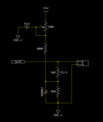
i've been implementing this schematic
and i can trim the DCout into 0v with very steady
and also the sound is very nice
there is one problem, with 1000uf caps equipped the gain reduced a lot,
i have to turn volume pot at 12'clock position to get a hearable sound
but if i uninstall the 1000uf caps the gain is normal, 8-9'clock position is hearable
why this 1000uf caps could reducing the gain?
thanks.
Peter
Attachments
Ooh, i see. Makes sense. I installed 100nf Murata c0g caps as well (but also kept the 100uf's in addition).Hi Zbunjen,
TDA1541 has internal DEM oscillator (on-chip timing capacitor, external timing cap pins are not connected), so the 50Hz mod can't work, the oscillator is fixed at approx. 200 KHz. The only option is using 100nF active divider decoupling caps.
Make sure to check JLsounds documentation & settings for the TDA1541 thoroughly, especially page 10, as it contains information about TDA1541 in simultaneous mode. Check if TDA1541 pin 27 is connected to -5V and that the 4K7 resistor is installed on the JLsounds board.
Perhaps it's best to start with I2S and try to get the circuit working, if it works, then proceed with simultaneous mode.
The crunch is now lower in volume but definitely still there, almost like a constant wind, and if you lower the volume all that's left is still just crunch.
I followed JLsounds documentation and can confirm its correctly setup for simultaneous and pin27 is jumpered to -5v.
Trying the I2s mode, i jumper p27 to +5v and reconfigure, it is a lot better but has crunch on low levels as well. Something is not normal here.
I thought maybe the chips are broken (i use 2x tda1541) in parallel, so i checked them individually (take one out, take other out), swapped them around, etc. but no difference.
There is a zip with 2 mp3 recordings, just showing how the crunch presents itself.
I am at a loss, this circuit is not so complicated, i implementned already 5-6 different R2R dac's, yet this one refuses to work...
Attachments
#8,065
6R8 resistor (part of DC bias correction) plus connected bias trimming resistors will increase effective I/V resistor value and related ac output voltage.
6R8 bypassed with 1000uF -> low impedance, almost zero Ohms -> 0.004mA ull scale current * 68R = 272mVpp audio output.
6R8 not bypassed and trimmer in centre position: 680R + 125R = 805 Ohms in parallel with 6R8 for ac signals so Rt becomes 6.74 Ohms.
(power supply is basically a short circuit for ac signals).
6R8 not bypassed -> Riv then becomes 68R + 6.74R = 74.74R -> 0.004mA ull scale current * 74.74R = 299mVpp audio output.
If you want to get the same output signal of 299mVpp -with- 1000uF installed, then the I/V resistor must be increased from 68R to say 75R (2 x 150R in parallel).
With 1000uF installed, power supply noise will be greatly attenuated and the output signal remains cleaner.
#8,066
The 100uF electrolytic capacitors need to be removed when using 200KHz DEM clock for correct DEM circuit operation.
The distortion from the examples is low level distortion and this suggests that the DEM circuit is not working correctly. It is unlikely that 2 chips have exactly the same problem, so the problem is most probably caused by the external components and circuits.
When you play a low level 1KHz test signal (-40dB ... -60dB) the distortion should be clearly visible on an oscilloscope as well. There is also quite some mains hum on the signal.
You could remove one of the 100nF active divider decoupling caps (nothing connected to that pin). Then measure the signal on that pin with an oscilloscope (ac millivolt range).
If DEM is working, there should be a kind of step signal on that pin. This confirms that the DEM oscillator is running and the switch matrix is working.
The shape of the step signal depends on passive divider mismatch. The passive divider is part of the active divider circuit.
This is different for each decoupling pin and different for each chip.
I attached a DEM measurement, the step signal at the bottom of attached picture shows how such step signal on a decoupling pin (decoupling cap disconnected) could look like.
The DEM decoupling cap will filter this step signal, leaving the average DC bit current of 4 slightly mismatched passive current divider outputs.
If for some reason these mismatched passive current divider outputs are not averaged, we get bit errors. Because these active dividers are on the 6 highest bits, slightest errors will be immediately audible and measurable. So correct DEM circuit operation is vital.
Thanks so much John you're a legend, i appreciate your time and help!#8,066
The 100uF electrolytic capacitors need to be removed when using 200KHz DEM clock for correct DEM circuit operation.
The distortion from the examples is low level distortion and this suggests that the DEM circuit is not working correctly. It is unlikely that 2 chips have exactly the same problem, so the problem is most probably caused by the external components and circuits.
When you play a low level 1KHz test signal (-40dB ... -60dB) the distortion should be clearly visible on an oscilloscope as well. There is also quite some mains hum on the signal.
You could remove one of the 100nF active divider decoupling caps (nothing connected to that pin). Then measure the signal on that pin with an oscilloscope (ac millivolt range).
If DEM is working, there should be a kind of step signal on that pin. This confirms that the DEM oscillator is running and the switch matrix is working.
The shape of the step signal depends on passive divider mismatch. The passive divider is part of the active divider circuit.
This is different for each decoupling pin and different for each chip.
I attached a DEM measurement, the step signal at the bottom of attached picture shows how such step signal on a decoupling pin (decoupling cap disconnected) could look like.
The DEM decoupling cap will filter this step signal, leaving the average DC bit current of 4 slightly mismatched passive current divider outputs.
If for some reason these mismatched passive current divider outputs are not averaged, we get bit errors. Because these active dividers are on the 6 highest bits, slightest errors will be immediately audible and measurable. So correct DEM circuit operation is vital.
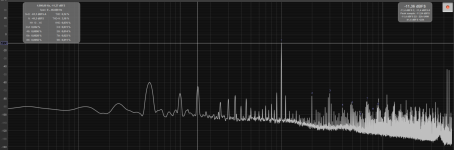
I went on to check the DEM currents as you described, while playing a low level signal.
Everything seemed fine, and similar to what you showed, i even played with the sample rate.
But then just out of sheer curiosity, i bridged the two pins used for DEM reclock, that say should not be connected (16 and 17) in non-A data sheet. Guess what! Completely solves it, but with FFT i found best is actually anything from 330pf to a couple of microfarad capacitor (with little change in this range). I put 2.7n C0G 1206 on both, and then paralleled the outputs, works like a beauty.
I also explored why there is such strong mains hum on the recording, it is actually related to the measurement cable going next to the mains cable, and you can audibly hear it appear and dissapear as you connect and disconnect the cable,so i dont think its there normally. I tried an audio isolator (so an isolation transformer) to see if its ground loop related, but no it made it even worse, so its likely just radiated emi pickup. I'll look into cables. The noise floor is suspiciously high, may or may not be related to this. Anyway harmonics are satisfactorily low, sound is smooth.
However the signed magnitude circuit from 7092 still struggling to get to work.
I got it to fart some 5bit music with LJ format but only with 92khz and above sample rate.
So i played around and sometimes it will fart music on other sample rates if i short bcko with tweezers on some IC's, or for example shorting U3 output to gnd.
Otherwise completely silent no matter which other I2S format i configure for jlsounds board or sample rate and bit depth (i went through all).
Changed which outputs of the circuit i take (SE or balanced) and all permutations.
Checked all solder points, and reflowed them, checked all IC orientation, voltages (tried 2.8-3.3v).
TDA1541 is set to simultaneous (27 to -5v) mode during all this of course.
Hmm.. i guess it would be impossible to troubleshoot something like this over messaging, i guess im hoping its something obvious and im just dense.. i quadruple checked the schematic...
I need to figure out how to screenshot the scope traces.
Did anyone else try this circuit in specific? @xaled ?
Hey Zbunjen,Thanks so much John you're a legend, i appreciate your time and help!
I went on to check the DEM currents as you described, while playing a low level signal.
Everything seemed fine, and similar to what you showed, i even played with the sample rate.
But then just out of sheer curiosity, i bridged the two pins used for DEM reclock, that say should not be connected (16 and 17) in non-A data sheet. Guess what! Completely solves it, but with FFT i found best is actually anything from 330pf to a couple of microfarad capacitor (with little change in this range). I put 2.7n C0G 1206 on both, and then paralleled the outputs, works like a beauty.
View attachment 1046988
I also explored why there is such strong mains hum on the recording, it is actually related to the measurement cable going next to the mains cable, and you can audibly hear it appear and dissapear as you connect and disconnect the cable,so i dont think its there normally. I tried an audio isolator (so an isolation transformer) to see if its ground loop related, but no it made it even worse, so its likely just radiated emi pickup. I'll look into cables. The noise floor is suspiciously high, may or may not be related to this. Anyway harmonics are satisfactorily low, sound is smooth.
Did anyone else try this circuit in specific? @xaled ?
Unfortunately I never had time to finish the board tests and make sure it runs with the TDA chip.
@koldby spent more time with one of my boards and if remeber it right got some positive results. You might want to search the thread for his comments to get the better picture.
Like starting from this page for example:
https://www.diyaudio.com/community/...ltimate-nos-dac-using-tda1541a.79452/page-354
And here as well:
https://www.diyaudio.com/community/...ate-nos-dac-using-tda1541a.79452/post-5750437
Last edited:
I spent some time today going through every post since #7092 just seeing if anyone at all even tried it, and that's pretty much right.
You made PCB but it's not tested, koldby used old sch and tacked on fix for phase offset, maxlorenz wrote some poetry, John has provided a lot of support and answers (quite a legend), but not much building going on.
Maybe lack is due to nobody has time to compile all info, and then make a board that you can just assemble and have working? I mean i already sunk quite some hours into this, who has this time..
So that's exactly what im doing now, maybe once i publish a working board something starts up again. Hmm...but then tda1541 prices might go up even more")
Now my options are:
1. Bang my head against the wall why it doesnt work, but with day job i dont have that much time. Or hope someone smarter sees the struggle..
2. Test your pcb to see if sch even works, but then i'd still have to make my new integrated pcb and test that again.
3. Make new pcb, i guess redo the schematic and layout again and hope first time was just some fluke.
4. Make new pcb, abandon 7092, use older version but with phase offset fix, at least 1 user ( @koldby ) tested so we know it should work in theory.
From this round of experimenting i got some ideas regarding some other stuff around the board too so....v1.1 is inbound anyway, think i'll maybe go with option 3 or 4. Maybe DM you later about option 2 to see how far we are, how bad is shipping and how i can reimburse you.
You made PCB but it's not tested, koldby used old sch and tacked on fix for phase offset, maxlorenz wrote some poetry, John has provided a lot of support and answers (quite a legend), but not much building going on.
Maybe lack is due to nobody has time to compile all info, and then make a board that you can just assemble and have working? I mean i already sunk quite some hours into this, who has this time..
So that's exactly what im doing now, maybe once i publish a working board something starts up again. Hmm...but then tda1541 prices might go up even more
Now my options are:
1. Bang my head against the wall why it doesnt work, but with day job i dont have that much time. Or hope someone smarter sees the struggle..
2. Test your pcb to see if sch even works, but then i'd still have to make my new integrated pcb and test that again.
3. Make new pcb, i guess redo the schematic and layout again and hope first time was just some fluke.
4. Make new pcb, abandon 7092, use older version but with phase offset fix, at least 1 user ( @koldby ) tested so we know it should work in theory.
From this round of experimenting i got some ideas regarding some other stuff around the board too so....v1.1 is inbound anyway, think i'll maybe go with option 3 or 4. Maybe DM you later about option 2 to see how far we are, how bad is shipping and how i can reimburse you.
I had the same crackling noise a couple of times with my project, see here, and can confirm that timing is important. Also DEM is delicate, try to make it work with free running DEM first.
And PCB cleaning was a big problem again and again: with the slightest remainings of flux under ICs I got crackling (as you said like wind noise)...
I needed to remove all ICs, bend their legs down a bit and solder them back to the board so that I can clean under them with paper stripes and a strong syringe etc., and drying also takes a lot of care...
Also the series resistors in the clock and data lines need to be of the correct value and at the right place. I am still impressed that digital audio is such a fragile thing.
So don't give up!
Last edited:
Hello, thanks for the words of encouragement.I had the same crackling noise a couple of times with my project, see here, and can confirm that timing is important. Also DEM is delicate, try to make it work with free running DEM first.
And PCB cleaning was a big problem again and again: with the slightest remainings of flux under ICs I got crackling (as you said like wind noise)...
I needed to remove all ICs, bend their legs down a bit and solder them back to the board so that I can clean under them with paper stripes and a strong syringe etc., and drying also takes a lot of care...
Also the series resistors in the clock and data lines need to be of the correct value and at the right place. I am still impressed that digital audio is such a fragile thing.
So don't give up!
For these tests, the I2S (and simultaneous) is ready served by the JLsounds I2SoverUSB board, so no flux related issues or series resistors added by me are employed for these two modes, this device is already pretty high level and worked perfectly with other DAC's i developed (stackable PCM56, AD1865, TDA1387, PCM1794 and so on...). This TDA1541 keeps being my most problematic but exciting project
The flux not being an ideal dialectric and having leakage currents between pins is something i did think about and consider with the implementation of the signed magnitude circuit and it was thoroughly brushed in acetone (previously tested that everything can withstand it, not even the printing on the IC's got off).
I dont think just having a cap between 16 and 17 by itself reclocks the DEM (even on non-A versions which i use here). But i am not sure why it completely fixes my problem when data sheet for non-A clearly says "not connected".
For completeness i setup the board in simultaneous mode, so now we know chips and everything else is setup fine for accepting this mode, safe to say problem is isolated to the logic now. Well, i must say i am at least somewhat happy, halfway there and this is still a nice sounding setup, but goal is not complete.
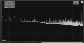
Also interesting, but measured performance seems identical to post 8069, at least as far as figures of merit go, both in spectra and levels of harmonic distortions. But my measurements right now aren't the best due to this mains stuff i still have to figure out why it appears there.
Also interesting, but measured performance seems identical to post 8069, at least as far as figures of merit go, both in spectra and levels of harmonic distortions. But my measurements right now aren't the best due to this mains stuff i still have to figure out why it appears there.
The flux not being an ideal dialectric and having leakage currents between pins is something i did think about and consider with the implementation of the signed magnitude circuit and it was thoroughly brushed in acetone (previously tested that everything can withstand it, not even the printing on the IC's got off).
I also thought that should be enough, but in my case it wasn't...
I dont think just having a cap between 16 and 17 by itself reclocks the DEM (even on non-A versions which i use here). But i am not sure why it completely fixes my problem when data sheet for non-A clearly says "not connected".
What if these were re-labelled -A chips? (Maybe even R1 ones...)
For completeness i setup the board in simultaneous mode, so now we know chips and everything else is setup fine for accepting this mode, safe to say problem is isolated to the logic now.
I can only repeat that my logic worked only after extreme cleaning and with the signal reflections on the transmission lines sorted...
Option 2 comes with all costs on meI spent some time today going through every post since #7092 just seeing if anyone at all even tried it, and that's pretty much right.
You made PCB but it's not tested, koldby used old sch and tacked on fix for phase offset, maxlorenz wrote some poetry, John has provided a lot of support and answers (quite a legend), but not much building going on.
Maybe lack is due to nobody has time to compile all info, and then make a board that you can just assemble and have working? I mean i already sunk quite some hours into this, who has this time..
So that's exactly what im doing now, maybe once i publish a working board something starts up again. Hmm...but then tda1541 prices might go up even more
Now my options are:
1. Bang my head against the wall why it doesnt work, but with day job i dont have that much time. Or hope someone smarter sees the struggle..
2. Test your pcb to see if sch even works, but then i'd still have to make my new integrated pcb and test that again.
3. Make new pcb, i guess redo the schematic and layout again and hope first time was just some fluke.
4. Make new pcb, abandon 7092, use older version but with phase offset fix, at least 1 user ( @koldby ) tested so we know it should work in theory.
From this round of experimenting i got some ideas regarding some other stuff around the board too so....v1.1 is inbound anyway, think i'll maybe go with option 3 or 4. Maybe DM you later about option 2 to see how far we are, how bad is shipping and how i can reimburse you.
I will also include my usb logic analyser if you'd promise to send it back
Every week i would go on local "used goods" site, with a text file of search terms such as "philips cd" or "rotel cd" and other brands that commonly implemented the TDA1541, the reasoning being it would throw up CDP line of players (and it did), then i'd sort by price and then check every listing which DAC it used (in 95% of cases it would be some early 2000s delta sigma), and after doing this many times i managed to score two players and take the chips out myselfWhat if these were re-labelled -A chips? (Maybe even R1 ones...)
A couple of times i went to a local flea market, but usually its always the same stuff there so i need to check in larger time intervals. All for the sole purpose of being step 1 of realising this project.Yes, always worth repeatingI can only repeat that my logic worked only after extreme cleaning and with the signal reflections on the transmission lines sorted...
Overall i did quite a bit revisions of the layout minding signal integrity, current returns, trace length and width, and to avoid vias for high speed signal when possible, not to mix trace sizes due to reflections, etc... New one will have yet a new layout, because what else to do.Xaled you are very nice, i think i will take you up on your offer.Option 2 comes with all costs on me
I will also include my usb logic analyser if you'd promise to send it back
I am quite confident if 7092 is valid logic, then your board will work, so it will be the final test of that.
So i will first test your board before proceeding further with getting new pcbs made. Based on results of that proceed accordingly.
Logic analyzer not needed, its due time i have one after seeing how it would come in handy now, so i ordered one, but thank you.
Obviously at the end of this road, all goes well, i'll send you my board on me too!
Every week i would go on local "used goods" site, with a text file of search terms such as "philips cd" or "rotel cd" and other brands that commonly implemented the TDA1541, the reasoning being it would throw up CDP line of players (and it did), then i'd sort by price and then check every listing which DAC it used (in 95% of cases it would be some early 2000s delta sigma), and after doing this many times i managed to score two players and take the chips out myself
Oh, if people do so no wonder that I never find a silver crown TDA1541A ;-)
Yes, always worth repeating
Good to hear my repeating was unnecessary
Did I mention I had to clean under the ICs to get the crackling noise disappear...?
BTW I found an old thread where a logic simulator with I2S data was discussed:
https://www.diyaudio.com/community/threads/tda_1541a-input-formats.25608/post-306074
Maybe it could be helpful to try to simulate the signed magnitude logic with it.
https://www.diyaudio.com/community/threads/tda_1541a-input-formats.25608/post-306074
Maybe it could be helpful to try to simulate the signed magnitude logic with it.
- Home
- Source & Line
- Digital Line Level
- Building the ultimate NOS DAC using TDA1541A