Interesting. I will try your suggestion although I can't say I have heard any obvious distortion. (probably I wouldn't given its -54db)
I assumed that a load resistor on the secondary would reduce the primary impedance (to 65R claim Sowter) which is in parallel with the I/V resistor, so although the output is at -200mv with no signal, at frequencies above about 10Hz, the 1541 sees a much lower resistance.
That is the issue - when You are using Riv and Transformer winding in parallel. Each connected at the Iout and GND. The current from dac chip will be divided on 2 parts. One part on Riv and other on Rdc (not the impedance) of the transformer wire winding. As the Rdc value of the winding is smaller, amount of current "converting" is higher. Plus it have additional effects (like EC explained) because this transformer Rdc is part of reactive net... And in that case non inductive Riv have less point.
.
But if You are using ballanced mode Riv off-course have to be at the Io - GND, but CT of the transformer should not be connected to GND. Only to DAC Io-s
In that case we have no current flow in the primary winding, no current caused by offset because the offsets are the same value. And avoiding reactance in the path of IV.
.
Neumann use this style a long time ago
") I tried it in praxis (many times) and for my op. is better. That is one of the advantages of BAL topology. Other could be - avoiding C at the direct path of the signal. If we dont count transformer capacitance...
I tried it in praxis (many times) and for my op. is better. That is one of the advantages of BAL topology. Other could be - avoiding C at the direct path of the signal. If we dont count transformer capacitance...
Last edited:
If somebody have Beyer Dynamics 1:1, small isolation transformer please try it. It is very very good sounding fellow. It is about 7000 ohms Rdc of the windings, about 1000 Hy primary inductance, and with a load of 47Kohms at the secondary, huge bandwidth without ringing and without overdamping of the output signal.
.
I will post the exact model marking later. Cant remember at the moment, sorry...
(Compared (listened) with Western Electric, some vintage types and contemporary interstagers)
.
I will post the exact model marking later. Cant remember at the moment, sorry...
(Compared (listened) with Western Electric, some vintage types and contemporary interstagers)
Last edited:
No! No CT and why should I ?Hi Koldby, thanks for the pics.
Did You connect center tap of the transformer (if You are using transformer with CT) to the ground?
Why do you need high bandwith at the output of a NOS DAC?If somebody have Beyer Dynamics 1:1, small isolation transformer please try it. It is very very good sounding fellow. It is about 7000 ohms Rdc of the windings, about 1000 Hy primary inductance, and with a load of 47Kohms at the secondary, huge bandwidth without ringing and without overdamping of the output signal.
.
I will post the exact model marking later. Cant remember at the moment, sorry...
(Compared (listened) with Western Electric, some vintage types and contemporary interstagers)
Transformer is only between the Iout of the DAC's, so no problem here as long as you load the secondary of the transformers a with relatively high impedance.That is the issue - when You are using Riv and Transformer winding in parallel. Each connected at the Iout and GND. The current from dac chip will be divided on 2 parts. One part on Riv and other on Rdc (not the impedance) of the transformer wire winding. As the Rdc value of the winding is smaller, amount of current "converting" is higher. Plus it have additional effects (like EC explained) because this transformer Rdc is part of reactive net... And in that case non inductive Riv have less point.
.
But if You are using ballanced mode Riv off-course have to be at the Io - GND, but CT of the transformer should not be connected to GND. Only to DAC Io-s
In that case we have no current flow in the primary winding, no current caused by offset because the offsets are the same value. And avoiding reactance in the path of IV.
.
Neumann use this style a long time ago
Hmmm.
Do we need the I/V resistors at all?
I think not.
When I was driving the trafos single ended, with bias, I had no I/V resistor from DAC out to ground, instead I had a resistor over the secondary (10K) and this , in turn, provided the load for the TDA1541.
The same is the case with the balanced TDA1541 when there has been established a 2 mA source for the output: No need for the 100 Ohm to ground! All the ac current from the two dac's will then go through the primary of the trafo and the load for the two DACoutput will be determined by the secondary resistor(s)
I will test it tomorrow.
Hmmm.
Do we need the I/V resistors at all?
I think not.
When I was driving the trafos single ended, with bias, I had no I/V resistor from DAC out to ground, instead I had a resistor over the secondary (10K) and this , in turn, provided the load for the TDA1541.
The same is the case with the balanced TDA1541 when there has been established a 2 mA source for the output: No need for the 100 Ohm to ground! All the ac current from the two dac's will then go through the primary of the trafo and the load for the two DACoutput will be determined by the secondary resistor(s)
I will test it tomorrow.
A few years ago when I was trying a quasi balanced mode by simply inverting the data to one channel of each TDA1541 (still in TWC mode) I needed I/V resistors or got no audio unless I grounded the CT which gave a DC path to 0V I assumed.
I think there does need to be a path to ground. If you had 2 current sources (or sinks) connected together, will current flow if there is not somewhere for it go i.e ground or the other supply rail? (if it was voltage rather than current, there wouldn't be an issue - eg speakers in BTL )
I never tried to cancel the offset so used 100R resistors and disconnected the CT from ground.
Last edited:
No! No CT and why should I ?
Did I said that You should (to connect CT)?
Why do you need high bandwith at the output of a NOS DAC?
Just because of the phase. I think that it is good thing to have minimum phase shift at the edges of BW.
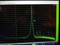
GROUNDING CT REDUCES DISTORTION..
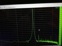
I tried an experiment in grounding the centre tap. The distortion at 1Khz was reduced by 2/3rds.
See traces - one channel has the CT grounded, the other doesn't. (I can't explain the peak at 1.84Khz.)
-9 to -12db was the optimum signal level and equates to about 2v p-p output from the Sowter transformer secondaries which is enough to drive my Quad 405 to full output with vol pot on max.
The signal generator is part of REW room equaliser software, and an el cheapo usb to I2S adaptor is used, and connected to the second I2S input on an IanCanada Fifo II.
I checked the sig gen output using the laptop's headphone output yesterday and although the SNR is poor, the distortion was lost in the noise at -50db.
My next step is too try current injection with the CT grounded or not.
Attachments
Were you grounding CT without applying 2 mA bias?I tried an experiment in grounding the centre tap. The distortion at 1Khz was reduced by 2/3rds.
See traces - one channel has the CT grounded, the other doesn't. (I can't explain the peak at 1.84Khz.)
-9 to -12db was the optimum signal level and equates to about 2v p-p output from the Sowter transformer secondaries which is enough to drive my Quad 405 to full output with vol pot on max.
The signal generator is part of REW room equaliser software, and an el cheapo usb to I2S adaptor is used, and connected to the second I2S input on an IanCanada Fifo II.
I checked the sig gen output using the laptop's headphone output yesterday and although the SNR is poor, the distortion was lost in the noise at -50db.
My next step is too try current injection with the CT grounded or not.
And is it a CT on the primary side?
You should never do that, you get DC through the trafos.
You have -200 mV DC at the output without bias.
Were you grounding CT without applying 2 mA bias?
And is it a CT on the primary side?
You should never do that, you get DC through the trafos.
You have -200 mV DC at the output without bias.
Yes it was primary CT and yes, I know it needs current injection to cancel the 2ma offset.
I was just curious. I wonder why the DC flowing did not increase the distortion?
I need a better software signal generator!
No you do not need a path to ground as long as you inject 2mA bias. And I think you actually have less conversion loss without the I/V resistors. All the AC current will flow through the primary of the trafos. In the case where you use 100 Ohm I/V resistors, some of the current goes through them to ground.A few years ago when I was trying a quasi balanced mode by simply inverting the data to one channel of each TDA1541 (still in TWC mode) I needed I/V resistors or got no audio unless I grounded the CT which gave a DC path to 0V I assumed.
I think there does need to be a path to ground. If you had 2 current sources (or sinks) connected together, will current flow if there is not somewhere for it go i.e ground or the other supply rail? (if it was voltage rather than current, there wouldn't be an issue - eg speakers in BTL )
I never tried to cancel the offset so used 100R resistors and disconnected the CT from ground.
No you do not need a path to ground as long as you inject 2mA bias. And I think you actually have less conversion loss without the I/V resistors. All the AC current will flow through the primary of the trafos. In the case where you use 100 Ohm I/V resistors, some of the current goes through them to ground.
I'll give the current injection and I/V resistor removal a try tomorrow.
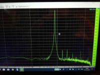
I checked my software sig gens via the heaphone output again.
NCH was 3% at best at 1kHZ and REW v5.1 was 1.5% at 1k.
Now plugging in the usb-I2S interface and from the transformer output, REW was .6% and .2% with the CT grounded so looks promising.
(With the CT not grounded at -10db there were 2nd & 3rd harmonic spikes visible but with it grounded these were lost in the noise.)
Hi everyone,
Just thought i'd share this, I recall John sharing this with me at some stage, although I haven't tried it yet.
Would be good for someone thinking of going down the transformer road but not wanting to invest heavily before giving it a try.
Just thought i'd share this, I recall John sharing this with me at some stage, although I haven't tried it yet.
Would be good for someone thinking of going down the transformer road but not wanting to invest heavily before giving it a try.
Attachments
Batteryman, what value of Riv-s You are using. And plese give us some data on the transformer? As I recognized form the text You are using bal mode, 2 x Riv, parallel primaries to Riv-s and Center tap conn to the GND?
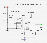
Each output of the balanced, simultaneous output TDA1541s has a 100R resistor and the transformer has dual primaries and secondaries (bifilar wound).
The primaries are in series from each of the I/V resistors with the CT not grounded. When I did ground them (briefly) distortion at 1KHz was 66% less.
The transformer is a Sowter 9545, which has been replaced with the similar 1465
1465 DAC Interface Transformer
I think Kolby is using the smaller 1495:
1495 DAC Interface Transformer
The secondaries are also in series, loaded by a 50k Alps pot in parallel with the 22k input resistance of a dc coupled Quad 405.
I have tried a 16k load resistor across the pot/windings, but I prefer it without.
I am going to try injecting the 2ma offset from a LiFePo4 cell to (avoid noise from the 5v supply) and then grounding the CT and also removing the I/V resistors.
(I'm still not convinced that its a good idea to remove them but I will try it)
Hi everyone,
Just thought i'd share this, I recall John sharing this with me at some stage, although I haven't tried it yet.
Would be good for someone thinking of going down the transformer road but not wanting to invest heavily before giving it a try.
I can see that method of providing a low impedance of +200mv at the other end of the 100R I/V resistor to cancel the offset might be a better way than just injecting a current from a higher value resistor.
Its another thing to try and now I have a means to measure the THD, IMD & Dynamic Range, the effects can be seen, though technical improvements do not of course, guarantee better sq.
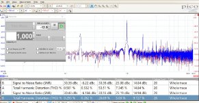
I cleaned up my measuring system with another input device.
All measurements are made with 2 mA bias.
First 0 dB digital with 100 Ohm from DAC out to ground and no secondary load resistor (Pic. 100 Ohm Riv)
Next 0 dB digital with no Riv and 56K secondary load resistor . This value made the same level out of DAC @ 0dB digital.
If I reduce the digital level with 10-12 dB all harmonics disappear in the noise...
Almost no difference.
Then I measured 0 dB digital with 10K secondary load resistor and more gain after the DAC.
Notice the 3. harmonic is reduced as a result of the lover level at the output of the DAC.
I am not sure it is noticeable sound-wise I have not listened carefully for a prolonged period.
It is only the 2. and 3. harmonic that comes from the DAC/Preamp the rest are there even if I turn off the Dac.
If I reduce the digital level with 10-12 dB (turning up the preamp gain ) the 2. and 3. harmonic disappears .
Attachments
- Home
- Source & Line
- Digital Line Level
- Building the ultimate NOS DAC using TDA1541A