What is the last good value of decoupling C? 100nF all 14?[/QUOTE
You will get confused after reading all posts of the gurus about it - ecdesigns, lampizator, ove and many others not so famous. Finally the best way seems to be deciding for yourself after many soldering/desoldering and listening
Cheers,
I believe Ian has made such a board:It was not easy but I managed to convert I2S 64 bits / frame (44.1/16) two’s complement into offset binary, 16 bit data bursts for TDA1541A in simultaneous mode.
5 bits counter plus decoder was used for clock stopping, discriminating the MSB “on the fly” to invert MSB only in the serial data stream (two’s complement to offset binary conversion) and to generate a LE pulse just before MSB.
/O0, Q1, Q2, Q3, and Q4 enter a NOR gate creating the MSB discrimination pulse.
O0, Q1, Q2, Q3, and Q4 enter a NOR gate creating the LE pulse.
WS, and Q4 enter a NOR gate for creating the BCK enable pulse.
The counter is clocked by BCK and reset with a one shot triggered by WS (synchronisation between conter and WS).
In order to complete the circuit I would need either a 32 bit delay circuit to align both L and R channels (simultaneous mode stereo), or a dual mono converter (simultaneous mode in dual mono).
Attached oscillogram shows the stopped clock BCK signal. Upper trace shows the WS signal, lower trace shows the periodic bit clock bursts (2.8224 MHz), each contains 16 BCK pulses.
The whole point of this exercise is to obtain longest possibe period of silence (absence of I2S interference in the TDA1541A and attached circuits) during each sample period.
I2S stream now looks as follows, LE pulse is generated, lasting one BCK clock cycle. 16 bits of data are clocked in simultaneously. Then the I2S stream is shut down completely (WS, DATA and BCK shut down for 75% of the sample period).
The created silence (absence of switching noise) has positive impact on sound quality.
http://www.diyaudio.com/forums/digi...ersal-i2s-pcm-driver-board.html#post3179225d:
Koldby
What is the last good value of decoupling C? 100nF all 14?
One solution from a friend of mine - 0.1 uf stiroflex - good sound.
Cheers
Attachments
I think the last ones that John used were those SMD 1uF from Cornell D - the polyester ones with the DEM running about the 60+kHz freq - not sure if this has stayed the same with the new developments
I've used a strange assembly with the Epcos B32529 1uF/63v (again polyester filter caps) - the first 3 pins (7,8,9) have 1uF, the next 3 (pins 10,11,12) have 2 of them in // (= 2uF) and the MSB (pin 13) has a 4uF Solen FC propylene cap (big ugly sucker!) and this is with the DEM running about 706kHz - quite noticeable improvements in both the bass clarity & grunt and the treble extension (that's not supposed to be available)
This works 'best for me', but is a bit unusual, so .....
Sounds very interesting and will try it asap. I am also funny with 1 uf on the LSB and 2.2 uf on the last two MSB - ELECTROLYTICS !?! directly on the TDA legs down there bypassed by 100 nano PPS on the board. So far sounds good but not proven by a scope /no knowledge/. Will increase the load on the three legs you suggest and inform results.
Cheers,
directly on the TDA legs down there bypassed by 100 nano PPS on the board. So far sounds good but not proven by a scope /no knowledge/. Will increase the load on the three legs you suggest and inform results.Cheers,
I found that the electrolytic caps caused a loss of detail, loss of transients, and were a backward step anywhere in the decoupling string (tried the BGs amongst others and some of those Sanyo ones too) but this might just be particular to my setup and the sound of your dac with those electros might be just what sounds right/best to you.
Even if it doesn't work okay, it's not hard to replace them with another cap plus you've learned something more about your system - a definite bonus.
All the best ....
Even if it doesn't work okay, it's not hard to replace them with another cap plus you've learned something more about your system - a definite bonus.
All the best ....
Right, thanks. Easy job-just unsolder one leg and see the details - bypassing cups stay. Will you post some pic of your TDA ?Even if it doesn't work okay, it's not hard to replace them with another cap plus you've learned something more about your system - a definite bonus.
Regards,
-
Are you serious ? No caps at all ??BTW I found the best is not to use any capacitor for DEM filtering.
This is a logical step: no oversampling - no analog filter - no DEM capacitors. Trying it is very easy...Are you serious ? No caps at all ??
Hi niamex,
oshifis only removed the 14 filter caps, not the “470pF”.
The idea is that the ripple frequency of fDEM and foldback into the audio spectrum (through crosstalk and jitter spectrum for example) is too high (approx. 200KHz and up, plus harmonics) to be audible.
With the measurable RF ripple voltage on the bit currents we might get a kind of dithering effect (added low level noise) that may result in a smoother sound.
OK I like the non standard way of thinking and will remove /temp/ the 470 pf cap to see what happens. Will keep you posted.
oshifis only removed the 14 filter caps, not the “470pF”.
The idea is that the ripple frequency of fDEM and foldback into the audio spectrum (through crosstalk and jitter spectrum for example) is too high (approx. 200KHz and up, plus harmonics) to be audible.
With the measurable RF ripple voltage on the bit currents we might get a kind of dithering effect (added low level noise) that may result in a smoother sound.
Hi niamex,
The 6K8 resistors can stay. These result in approx. 3Vpp clock signal amplitude making it less sensitive to on-chip switching noise. This in turn reduces noise and deterministic jitter on the DEM clock.
I use a DEM frequency of around 900 KHz now (2 * 6K8 plus a silvered mica SMD 100pF timing cap) and 14 * 330nF 1206 size SMD film caps for filtering.
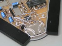
I cut off the thin part of the TDA1541A pins and soldered the chip directly to the PCB. The film caps are soldered very close to the pins (few millimeters) and to the solid ground plane on the other side of the PCB (attached pictures).
Many thanks, wrong understanding /ignorance/, will keep learning Than the 6K8 also have to disappear ?
The 6K8 resistors can stay. These result in approx. 3Vpp clock signal amplitude making it less sensitive to on-chip switching noise. This in turn reduces noise and deterministic jitter on the DEM clock.
I use a DEM frequency of around 900 KHz now (2 * 6K8 plus a silvered mica SMD 100pF timing cap) and 14 * 330nF 1206 size SMD film caps for filtering.
I cut off the thin part of the TDA1541A pins and soldered the chip directly to the PCB. The film caps are soldered very close to the pins (few millimeters) and to the solid ground plane on the other side of the PCB (attached pictures).
Attachments
Hi Oshifis,
You were right, I have corrected my mistake /tks to John/ and removed the 14 caps there - first impression is good ! So many diferent approaches here - I am getting confused - but you know the bad feeling havent trying all options
Thanks and regards,
Ignat
This is a logical step: no oversampling - no analog filter - no DEM capacitors. Trying it is very easy...
You were right, I have corrected my mistake /tks to John/ and removed the 14 caps there - first impression is good ! So many diferent approaches here - I am getting confused - but you know the bad feeling havent trying all options
Thanks and regards,
Ignat
- Home
- Source & Line
- Digital Line Level
- Building the ultimate NOS DAC using TDA1541A