The second i/v stage is used to sum the two signals of the first i/v stage. But wouldn't it be easier to use a transformer to sum the two signals? Using a step down transformer, you can have 2VRMS output without the entire 2nd stage.
If using tubes is an objective, we can use a couple DHT (say 801A) PP as I/V first stage. Now DHT Dac -- that should qualify as ultimate.
If using tubes is an objective, we can use a couple DHT (say 801A) PP as I/V first stage. Now DHT Dac -- that should qualify as ultimate.
Re: octal D-I DAC improvements
No worries. As people here well know, I am a pretty critical
b@stard, but definately will give praise where due.
Jitter has no effect on digital filter performance. When designed
correctly, the DAC should be reclocked with clean extracted clock
signal, so any jitter introduced by DF is negated.
Have you compared I2S to SPDIF IP, and found little difference?
I havent tried this yet and it's on the 'to do' list. However everyone
so far has been very positive about this mod.
If the opamps stages are pefect, then why do you need the tube
stage aswell? I am not being negitive, just something to think
about.
We both know that the tube stage is adding something euphonic,
so the question is, can the dac sound it's best without this added
and is it necessary?
Again I don't want to appear negitive, just probing the "why's"
of a particular design result.
The S/N or DR of the dac is fairly easy to calculate but not much
point here. . Having the 8 chips summed with such low impedances
and high voltage OPs will have a big DR as you have pointed out.
But to put it in perspective, just 1 x TDA1541 feeding a 627 will have
a noise floor far lower than any of the mic preamps thermal noise
floor used in the recording even at 16bits.
So generally for any well designed dac, noise is never an issue.
However I think you are referring to "perceptual noise" of the
dac, it's ability to pick up fine details in the recording below
the recordings noise floor, yes?
I think your solution is a good one considering you have the OP
of 4 dacs per side to contend with.
From all the previous 0 feedback and discrete I-V circuits posted
here at DIYA, I have not seen any that would deal adequately with
your front end. Too much current swing and too low a source
impedance will mean very non linear result.
Only a properly designed, fully balanced current conveyor circuit
that will handle the large current swings with a low source
impedance will work satisfactorily IMO. It would require a very
application specific approach and much care. However I still contend
that the results should be well worth it.
I am interested in getting a few pcbs for the front end off you if they
become vailable and doing my own discrete balanced O FB I-V
stages.
Again, very good work EC.
Cheers
Terry
-ecdesigns- said:Hi Terry Demol,
Thanks for your compliments [post#329],
No worries. As people here well know, I am a pretty critical
b@stard, but definately will give praise where due.
The octal D-I DAC design is constantly veryfied by measurements (shown on this thread), many listening sessions, and by comparing it with my NOS reference DAC. Circuits have been modified / optimized many times to get optimal verifyable results.
> I use a differential SPDIF input signal, and have modified my CD player by adding a differential RS422 output stage [post#268]. So jitter is very low, as the CS8412 PLL runs very stable due to the stable SPDIF input signal. Guido's XO DAC PLL seems to be used often to upgrade a standard oversampling CD player containing a digital filter. I can imagine that a jittery clock can affect digital filter operation, and adding a XO DAC PLL can significantly improve sound quality.
Jitter has no effect on digital filter performance. When designed
correctly, the DAC should be reclocked with clean extracted clock
signal, so any jitter introduced by DF is negated.
I could easily reserve some space on the digital mainboard for a jitter reduction module if desired.
However, the octal D-I DAC is quite special compared to other DAC concepts. It's completely filterless, no digital filter, no analog filter, and uses no oversampling. All 8 DAC chips are running on a relaxed 2.8224 MHz BCK. The timing chain seems to have an averaging effect on jitter as well, as the clone samples appear at the output after n*BCK delay . All these octal D-I DAC properties seem to make it relatively immune to jitter, this can easily be verified by listening sessions.
Have you compared I2S to SPDIF IP, and found little difference?
> Yes DEM clock synchronizing with BCK has made a big improvement, especially in improved clarity and detail.
I havent tried this yet and it's on the 'to do' list. However everyone
so far has been very positive about this mod.
> The OP-amp I/V stages are highly optimized, they have very low distortion as can be seen in [post#269] oscillograms. Output is a near perfect step signal without ringing or sagging, indicating feedback causes no appearent problems here.
If the opamps stages are pefect, then why do you need the tube
stage aswell? I am not being negitive, just something to think
about.
We both know that the tube stage is adding something euphonic,
so the question is, can the dac sound it's best without this added
and is it necessary?
Again I don't want to appear negitive, just probing the "why's"
of a particular design result.
The unity-gain diff amp cancels out the last bits of interference and the large DC offsets from both non-inverted and inverted DAC chip groups. It's output signal high frequency rolloff is matched to the tube output stage. Output signal is now about 18 Vpp, (taking full advantage of the +/- 15V power supply). The signal can now be attenuated close to the RCA socket for optimal SN ratio. Basically if you hear the octal D-I DAC producing noise, it's on the CD recording, yes even studio recording equipment noise is reproduced accurately, microphones picking-up radio stations "hidden" in the noise, included.
The S/N or DR of the dac is fairly easy to calculate but not much
point here. . Having the 8 chips summed with such low impedances
and high voltage OPs will have a big DR as you have pointed out.
But to put it in perspective, just 1 x TDA1541 feeding a 627 will have
a noise floor far lower than any of the mic preamps thermal noise
floor used in the recording even at 16bits.
So generally for any well designed dac, noise is never an issue.
However I think you are referring to "perceptual noise" of the
dac, it's ability to pick up fine details in the recording below
the recordings noise floor, yes?
I have already tried a lot of different setups, passive I/V, several I/V stages with discrete components both FET's and transistors, with and without feedback.
I think your solution is a good one considering you have the OP
of 4 dacs per side to contend with.
From all the previous 0 feedback and discrete I-V circuits posted
here at DIYA, I have not seen any that would deal adequately with
your front end. Too much current swing and too low a source
impedance will mean very non linear result.
Only a properly designed, fully balanced current conveyor circuit
that will handle the large current swings with a low source
impedance will work satisfactorily IMO. It would require a very
application specific approach and much care. However I still contend
that the results should be well worth it.
I am interested in getting a few pcbs for the front end off you if they
become vailable and doing my own discrete balanced O FB I-V
stages.
Again, very good work EC.
Cheers
Terry
The transistor radio issue
Hi dddac,
Thanks for your reply [post#338],
> The posted schematic diagrams are concepts, it basically shows the setup I am testing right now. There are many different aproaches to the output stage and diff amps, and the modular setup makes it easy for DIY members to experiment with different setups. The input impedance of my control amplifier is approx. 40KOhm, interlink is 60cm. The output impedance in mixed mode with the current setup is approx. 5KOhm. Limiting factor here is the cathode follower, but with the current impedance and setup, I don't encounter the problems you mentioned.
> The second comment made you grinz a bit, I already regret I made that remark. I just got a bit exited about the improvements made in sound quality, that's all. I intend to arrange some listening sessions with DIY members soon, to clear this issue.
This is my "checklist" containing the major parameters to check sound quality, every time I make a modification, it takes about 2-3 hours to check:
- All music genres should be reproduced correctly
- The sound must be fully transparent, open, it should come alive, you should have the impression, the artists are standing right next to you
- Sound reproduction must be natural and relaxed, listening at (very) high volume settings may not cause listening fatigue
- The sound should come close to that of live music (I use live jazz recordings and Chesky audio recordings to verify)
- Sound must be harmonic, just a single tone must be able to set free emotions
- High frequencies (high-hat cymbals, strings, maraccas, Rhythm Triangles, Wind Chimes) must be reproduced crystal clear and realistic
- S-sounds must be reproduced without any "hissing"
- Midrange should be clearly present, it should sound warm, never harsh
- Bass reproduction must be accurate and natural, preferably it must go way down near subsonic range, without sounding wooly
- Each bass frequency shift must be clearly audible
- Instruments timbre must be clearly heared
- Every last bit of detail must be clearly audible
- One must be able to "follow" each single instrument wit ease, even when many instruments are being played at the same time
- Dynamic range should be as high as possible
- System should respond very fast
- Hum levels should be low, (sonic resonators will reveal hum immediately)
- Noise levels should be low, only recorded noise should be audible
- The entire frequency range must be perfectly balanced
- Details about the acoustic space should be reproduced accurately
- When listening at larger distances (other room), the perceived sound shouldn't change significantly
So I think I got the most important aspects of sound quality covered. After all it's the perception of sound quality that's important. A circuit with excellent specifications is not always a guarantee for excellent sound quality.
> I have heared SACD players several times, and despite the high resolution, I am a bit dissapointed by their sound quality. When comparing it to the octal D-I DAC you are comparing both, 2 different systems (1 bit 2.8224 MHz relative sampling / 16 bit 44.1 KHz absolute sampling), and different DAC parameters.
> Thanks, I will certainly keep up the good work, I am trying to work out a very interesting digital module right now, the DXCPL
Instrumentation OP-amps
Hi PinkPanther-2
thanks for your tip [post#340],
SSM2019: 3 OP-amps, typical distortion 0.008%, slewrate 20V/uS, noise 1.3nV, bandwith 3.4MHz
INA217: 3 OP-amps, typical distortion 0.004%, slewrate 15V/uS, noise 1.3nV, bandwith 3.4MHz
OPA627: 1 OP-amp, typical distortion 0.00003%,slewrate 55V/uS, noise 4.5nV, bandwith 16MHz
I use the OPA627 for it's low distortion, resolution and clarity, open sound and increased bass performance.
This is backed-up by several reviews of this chip on the internet.
Disadvantages:
- noise of 4.5nV (no problem in this application)
- Quiescent current of 10mA (produces more heat / SMD)
- Relatively high price
Hi ECdesigns,
Absolutely cracking DAC! Really impressive!
I admit, my sampling theory does make me wonder if this design can be accurate, but perhaps the fact that the lack of a large nth order antialiasing filter, so the phase errors are small, dramatically outweighs the potential concerns of sampling inaccuracies (due to shannons law etc). Anyway, if people like it, and the design has some logic behind it, why worry? Its definitely interesting, whether you believe it should work or not.
Anyway, showing my ignorance here, after seeing it mentioned here I've been trying to find a 'beginners guide' to DEM reclocking. I seem to be a bit confused by it I'm afraid.
Do the output pins of the DEM reclocking circuit (labelled DEM_pin) connect to the two pins use for the 470pF capacitor? Or have I missed the point?
If so, do you need one circuit per DAC chip?
Sorry to lower the IQ of this great thread, but I just wanted to get that clear.
I'm hopefully going to order some TDA1541As and start experimenting with them. I am probably going to feed them I2S, fed from an old Marantz CD41 to start with. I want to convert to optical and use three optical cables to send the I2S
Should be fun.
Thanks for the insight.
Cheers,
Phil
Hi All!
Yes, Ecdesigns, you are perfectly right - OPA 627/37 are the best Op Amps. There is no doubt. But are expensve, too. This year Texas Instrumens don't offer more free samples from those excellent OpAmps and this is one of the reasons why there are so many questions about this stage in this thread.
Otherwise I like this "Burr-Browndog" combination...
Transformer output
Hi agent.5,
Thanks for your tip [post#341]
> Yes this could be done, and I have seen some setups like this on the internet. It's certainly worth a try, same I/V diff amp module could be used, removing the OPA627 diff amp chip and using the I/V outputs I already provided on the analog mainboard connector. No problem at all. However, the audio signal would no longer be DC-coupled.
> Using tubes is not my objective, it started as a experiment. Then I was surprized by the open and transparent sound of the tube diff-amp, I couldn't get this effect with semiconductors. Then I tried to rule out tube distortion as a cause to this effect, by optimizing the tube output stage using high amplitude triangle waves from a DDS generator. The tube output stage is used for the diff-amp only, As indicated earlier, I only use mixed mode now. It's difficult to exactly explain how the added tube output stage affects sound quality. It seems to compensate for something that was missing or something that slightly distorted the signal. I couldn't get this effect with semiconductors only, nor tubes only, you do need both.
critics
Hi Terry,
Thanks for your reply [post#342]
> I don't mind critics at all, as it often results in (significant) improvements. It also gives new impulses for design strategy.
> SPDIF Jitter is being taken care of, the DXCPL module is currently being developed. It contains a fixed stable crystal oscillator, and a digitally "stepped" phase locking circuit. Phase locking is done by digitally delaying BCK,DATA and WS, until they run synchronous with the fixed crystal oscillator.
> I am still waiting for the PCM2706 chip, when it arrives, I can experiment with the USB to I2S interface module.
> I will post a complete schematic diagram for the DEM clock synchronizing I am using on the analog mainboard
> The mixed mode (Tube + OP-amp) resulted in a sound quality I never experienced before with my set. The tube stage is only partly involved in the mixed mode and has very low distortion, the added component must be very minimal, but it still gives quite an improvement. As I already mentioned, it seems to compensate for something missing in the audio signal. I don't get this effect with OP-amp nor tube mode.
> Noise: When I pause the CD player and turn the volume to maximum, there is only slight noise produced both in tube and mixed mode. OP-amp mode noise can hardly be heared at maximum volume.
Now let me try to explain what I hear, First when a track is started there is silence (datastream is already running), then the (studio) recording noise appears (sounds different and has different amplitude with each recording), then the music starts. After the music stops, the studio recording noise remains, then the sound goes silent again. With a recording of Diana Krall, love scenes, I can clearly hear the microphone's noise cancelling circuit switching-on and off all the time. So within the recorded noise (yes the noise is recorded and present on the CD), lot's of details are still audible, like hum, oscillations, faint picked-up radio transmissions and interference of the recording equipment. Remember, the octal D-I DAC is completely filterless, so all these details start appearing.
Cheers,
John
Spectrum analysis
Hi Bernhard,
Thanks for your reply [post#343],
You are referring to addittional harmonics apearing in the FFT spectrum due to jitter I suppose. With my Tectronics scope the FFT scan looks quite good, hardly any addittional spikes. Sound quality backs this up. But to put everybody who is very concerned about jitter at ease, I am currently developing a fully digital jitter elimination circuit using a stable crystal oscillator and a stepped digital phase locking circuit, the DXCPL module.
Re: Transformer output
which amplifiers and speakers do you use? I assume there is no pre-amp.
It's difficult to exactly explain how the added tube output stage affects sound quality. It seems to compensate for something that was missing or something that slightly distorted the signal. I couldn't get this effect with semiconductors only, nor tubes only, you do need both.
which amplifiers and speakers do you use? I assume there is no pre-amp.
DEM synchronizing schematics (new)
Hi Phil,
Thanks for your compliments [post#346]
> Yes, you're right, by using interpolation, errors occur. Question is how do they affect sound quality, can it hardly be noticed or is it more problematic. With the current setup using mixed mode, errors seem to have hardly any effect on the perceived sound quality.
As we say over here in Holland, people who ask questions can be helped.
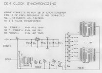
> So I specially made a schematic diagram of the DEM clock synchronizing circuit used in the octal D-I DAC analog mainboard, this should answer your questions about this circuit. Only pin 16 is connected to the DEM clock trough a 470pF capacitor, pin 17 is not connected. You only need one circuit for all DAC's. If both the LCL filters and pulse transformer should be difficult to obtain, R2 can be directly connected to R3 (bypassing the filter), but this slightly increases noise levels.
> Have you also considered differential RS422 interfaces for the I2S signals? separate fibre optics can cause phase problems (toslink).
Cheers,
John
Hi Phil,
Thanks for your compliments [post#346]
> Yes, you're right, by using interpolation, errors occur. Question is how do they affect sound quality, can it hardly be noticed or is it more problematic. With the current setup using mixed mode, errors seem to have hardly any effect on the perceived sound quality.
As we say over here in Holland, people who ask questions can be helped.
> So I specially made a schematic diagram of the DEM clock synchronizing circuit used in the octal D-I DAC analog mainboard, this should answer your questions about this circuit. Only pin 16 is connected to the DEM clock trough a 470pF capacitor, pin 17 is not connected. You only need one circuit for all DAC's. If both the LCL filters and pulse transformer should be difficult to obtain, R2 can be directly connected to R3 (bypassing the filter), but this slightly increases noise levels.
> Have you also considered differential RS422 interfaces for the I2S signals? separate fibre optics can cause phase problems (toslink).
Cheers,
John
Attachments
tube vs opamp
Imo its the content of harmonics, opamps can sound good (even the good-old 5532!) but only tubes can give that "something special" on the sound. Experienced this when i rebuilded the poweramp's opamp voltage stage into a E88CC stage, and the current stage kept the same powerfets(hitachi 2SJ135/2SK..) With the tube stage the sound is more natural and detailed compared to the SS voltage stage.
And its not a bad idea to combine opamps with tube stages, to equally nivelate odd harmonic stages (SS/opamp) with even harmonic stages(tube)
The perceived sound spectrum is more complete with tubes, with opamps and SS there seems to be a small "hole" in the high mid frequency range (around 4000Hz)
This is still my point of view.
Thanks for dem schematic Ecdesigns, i tried it allready on the 304(your written version), but some problems has to solved. The display works again, i can get the CDP in service position A and B to service.
Why so many transformers?
It's difficult to exactly explain how the added tube output stage affects sound quality. It seems to compensate for something that was missing or something that slightly distorted the signal.
Imo its the content of harmonics, opamps can sound good (even the good-old 5532!) but only tubes can give that "something special" on the sound. Experienced this when i rebuilded the poweramp's opamp voltage stage into a E88CC stage, and the current stage kept the same powerfets(hitachi 2SJ135/2SK..) With the tube stage the sound is more natural and detailed compared to the SS voltage stage.
And its not a bad idea to combine opamps with tube stages, to equally nivelate odd harmonic stages (SS/opamp) with even harmonic stages(tube)
The perceived sound spectrum is more complete with tubes, with opamps and SS there seems to be a small "hole" in the high mid frequency range (around 4000Hz)
This is still my point of view.
Thanks for dem schematic Ecdesigns, i tried it allready on the 304(your written version), but some problems has to solved. The display works again, i can get the CDP in service position A and B to service.
Why so many transformers?
Audio set used during octal D-I DAC testing
Hi agent.5
Thanks for your reply [post352]
The tube output stage is the one used in the octal D-I DAC
> I use a 6 channel control amplifier [post#209], basically containing a attenuator and a OPA627 unity gain buffer. Channels L, R, LR, RR, centre and subwoofer channels. Currently I only use 2 channels.
> A fully symetrical 2 X 70W cascode MOSFET power amplifier is used [post#208] with floating ground, no relays. It uses NON-inductive stranded copper wire resistors in the power output stage and two single MOSFET's, 2SJ201 and 2SK1530. The input circuits contain 2SJ109 and 2SK389. Power is limited to 2 X 70W because of the very high efficiancy of the sonic resonators, higher power would become dangerous.
> For speakers I use sonic resonators version2, [post#8] shows an early prototype and explains how it works. They are 360 degree omnidirectional radiators. Passive filter includes stranded copper wire resistors, stranded wire coils and stranded wire interconnections, Audin TIN capacitor (tweeter) and NON-inductive Audyn Plus capacitors. The speaker cables are also stranded wire types.
Harmonics / coils in DEM clock circuit
Hi tubee,
Thanks for your explanation [post354]
> Good explanation tubee. This might just be what happens. This could explain the natural sound in the mixed mode, that couldn't be achieved with only tube or only OP-amp stage.
> why so many transformers? The output signal form the 74HCT161 contains interference superimposed on the signal, I use 2 LCL filters to attenuate this interference. The pulse transformer is used to prevent noise of the digital ground entering the analog ground on the TDA1541A side (reference for the DEM clock) as this technique gave best results. The TDA1541A digital ground is used as reference for the I2S input signals. I used the same circuit for the analog mainboard.
Hi John,
Thanks for the schematic, that's completely cleared the confusion.
I can now go off and understand it properly, now that I have a frame of reference.
I did consider doing a differential driver for I2S, perhaps using a 9pin D connector and a bundle of shielded twisted pairs, but I thought it might be quicker and easier to just get 3 optical drivers (at the moment, I just want to get playing with DACs relatively quickly).
I didn't think there'd be a phase issue, but I guess it is plausible with low end optical fibre.
Thanks again for the diagram.
Cheers,
Phil
dem reclock
Ok thanks for explanation Ecdesigns, i will see if it its nescesary to improve the dem reclock, my first try was on the 304mk2, and it works. The uprocessor has some faults, but in service position it plays discs.
I reclocked Mcl on SAA7210 decoder, reclocked SAA7220 separate also, reclocked the 1541dac (/2) and dem-reclocked it also. All with 163 dividers. And it works! So far i can hear on headphones there is less glare, slightly better soundstage/depth. Btw kept the 5532 in it, but putted in sockets to exchange ic's later.
When the uprocessor is allright i can listen to it on my speakers again. Shall do a selftest of uP to check them.
Re: Spectrum analysis
No, nothing with jitter.
Just measure with this file, at - ??? dB is strongest harmonic when 1kHz set to reference level ?:
http://www.pedjarogic.com/files/1kHz-60dB_dithered_nshaped.zip
-ecdesigns- said:Hi Bernhard,
Thanks for your reply [post#343],
You are referring to addittional harmonics apearing in the FFT spectrum due to jitter I suppose. With my Tectronics scope the FFT scan looks quite good, hardly any addittional spikes. Sound quality backs this up. But to put everybody who is very concerned about jitter at ease, I am currently developing a fully digital jitter elimination circuit using a stable crystal oscillator and a stepped digital phase locking circuit, the DXCPL module.
No, nothing with jitter.
Just measure with this file, at - ??? dB is strongest harmonic when 1kHz set to reference level ?:
http://www.pedjarogic.com/files/1kHz-60dB_dithered_nshaped.zip
Project update
Hi tubee,
Thanks for your reply [post#358]
Glad to hear the DEM clock synchronizing caused improvements. If you don't use the last schematic diagram, some noise may be added to the signal. If you are looking for a affordable replacement for the NE5532, why not try a OPA2132 (dual), I tested those earlier and they are not bad. Specs: FET input unity gain stable, typical distortion 0.00008%, noise 8nV, bandwith 8MHz, slewrate 20V/uS. Single version is the OPA132
I have a project update as well,
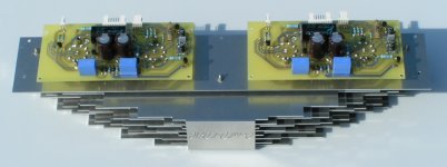
The printed circuit boards for the tube output stage are ready and tested, I seem to make a lot of mistakes lately, looks like a definately need a rest. I managed to reverse polarity 2 zener diodes and 2 capacitors. Same error is in the last schematic diagram of the tube output stage I posted, D4, D5, C5 and C7 are polarity reversed. This resulted in a lot of extra work taking everything apart again and correcting this error. Due to the 2K2 current limiting resistor nothing went up in smoke. I added a photograph of both tube output stage modules mounted on the grille.
Hi tubee,
Thanks for your reply [post#358]
Glad to hear the DEM clock synchronizing caused improvements. If you don't use the last schematic diagram, some noise may be added to the signal. If you are looking for a affordable replacement for the NE5532, why not try a OPA2132 (dual), I tested those earlier and they are not bad. Specs: FET input unity gain stable, typical distortion 0.00008%, noise 8nV, bandwith 8MHz, slewrate 20V/uS. Single version is the OPA132
I have a project update as well,
The printed circuit boards for the tube output stage are ready and tested, I seem to make a lot of mistakes lately, looks like a definately need a rest. I managed to reverse polarity 2 zener diodes and 2 capacitors. Same error is in the last schematic diagram of the tube output stage I posted, D4, D5, C5 and C7 are polarity reversed. This resulted in a lot of extra work taking everything apart again and correcting this error. Due to the 2K2 current limiting resistor nothing went up in smoke. I added a photograph of both tube output stage modules mounted on the grille.
Attachments
- Home
- Source & Line
- Digital Line Level
- Building the ultimate NOS DAC using TDA1541A