Ot 26
Bias
with the 26 (1 amp filament) and want a bias of 10v , I use a 10 ohm resistor at 10 watts so that resistor has to be about 25 watts...
linkhttp://www.diyaudio.com/forums/tubes-valves/151421-26-pre-amp-13.html#post2222723
the best power resistor ?
this guys still working on grid bias..
Bias
with the 26 (1 amp filament) and want a bias of 10v , I use a 10 ohm resistor at 10 watts so that resistor has to be about 25 watts...
linkhttp://www.diyaudio.com/forums/tubes-valves/151421-26-pre-amp-13.html#post2222723
the best power resistor ?
this guys still working on grid bias..
Last edited:
Do you hear the DJA?
Hi John,
Yes, I'm familiar with jitter calculations. My question to you is what do you hear with the DJA in circuit, versus the DJA out of circuit? Do you find the DJA audible, or does it present only a theoretical improvement? If it is audible, how would you describe it's affect on the sound?
Thanks,
Ken
Hi Ken,
So despite the fact that timing deviations (jitter) are extremely small compared to the audio range, their effect on pulse energy can easily lead to reduced bit resolution.
Hi John,
Yes, I'm familiar with jitter calculations. My question to you is what do you hear with the DJA in circuit, versus the DJA out of circuit? Do you find the DJA audible, or does it present only a theoretical improvement? If it is audible, how would you describe it's affect on the sound?
Thanks,
Ken
Hi Ken,
The DJAs clearly improve sound quality, this is immediately audible. I even added a second one to feed the masterclock to the synchronous bit reclocker.
The name DJA doesn't fully describe the function of this circuit. The circuit performs following:
- Clock signal rectifier (required when clock signal goes negative with respect to GND). Rectifier is also required to create DC bias voltage.
- Electronic switch (disconnects clock load before input clock signal reaches zero). This halves clock load and interference (low capacity coupling < 0.5pF during switch-off period).
- DC bias for the clock signal (prevents clock signal from going below specified threshold level). This reduces ground-bounce in connected circuit
- Dynamic jitter attenuator (converts timing deviations into ripple voltage that is used for pre-compensation for triggering).
- Decorrelator (Adds specified amount of white noise to decorrelate clock / source jitter).
- Damping (includes damping resistor to reduce ringing).
- Attenuator (attenuates clock signal in order to reduce ground-bounce).
The improvements include better transparency, cleaner bass, more micro detail, smoother sound (less grain), better focus.
I improved the DJAs using fast Schottky RF diodes (low junction capacitance) and combination of different diodes to accurately tune the noise spectrum.
I also improved RF ... UHF filtering using ferrite bead strain filters. These consist of up to 15 ferrite beads on a wire that is folded like a choke. It's basically a choke made of ferrite covered wire. The ferrite beads screen the wire from external EM fields while attenuating EM fields emitter by the signal that passes the wire. The ferrite strain was formed into a choke to save space.
Yes, I'm familiar with jitter calculations. My question to you is what do you hear with the DJA in circuit, versus the DJA out of circuit? Do you find the DJA audible, or does it present only a theoretical improvement? If it is audible, how would you describe it's affect on the sound?
The DJAs clearly improve sound quality, this is immediately audible. I even added a second one to feed the masterclock to the synchronous bit reclocker.
The name DJA doesn't fully describe the function of this circuit. The circuit performs following:
- Clock signal rectifier (required when clock signal goes negative with respect to GND). Rectifier is also required to create DC bias voltage.
- Electronic switch (disconnects clock load before input clock signal reaches zero). This halves clock load and interference (low capacity coupling < 0.5pF during switch-off period).
- DC bias for the clock signal (prevents clock signal from going below specified threshold level). This reduces ground-bounce in connected circuit
- Dynamic jitter attenuator (converts timing deviations into ripple voltage that is used for pre-compensation for triggering).
- Decorrelator (Adds specified amount of white noise to decorrelate clock / source jitter).
- Damping (includes damping resistor to reduce ringing).
- Attenuator (attenuates clock signal in order to reduce ground-bounce).
The improvements include better transparency, cleaner bass, more micro detail, smoother sound (less grain), better focus.
I improved the DJAs using fast Schottky RF diodes (low junction capacitance) and combination of different diodes to accurately tune the noise spectrum.
I also improved RF ... UHF filtering using ferrite bead strain filters. These consist of up to 15 ferrite beads on a wire that is folded like a choke. It's basically a choke made of ferrite covered wire. The ferrite beads screen the wire from external EM fields while attenuating EM fields emitter by the signal that passes the wire. The ferrite strain was formed into a choke to save space.
Hi fff0,
The regulator low output impedance (large bandwidth) is already lost after a few cm of PCB trace. The regulator also can't possibly maintain low output impedance up to a few GHz, it only has limited bandwidth. So what happens is that at a certain frequency the impedance rises rapidly again.
I feed selected low noise regulators with cleanest possible DC voltage (3-stage stepped rectifiers followed by a capacitance multiplier and passive LC filtering).
The main reason conventional regulators usually perform poorly is the ripple and noise on their input voltage. The regulator then needs to correct both, the noise at the input and the noise at the output. This is too much for a regulator with limited bandwidth.
The regulator noise can be easily reduced to acceptable levels by connecting large enough capacitor value at the regulator output. I use 1500uF.
The regulators also provide protection (over-voltage / short circuit / thermal overload).
Finally the size of the regulators is an advantage. It allows to construct compact circuits with shortest possible connections.
After the regulator I add some more passive filters and dissipative ferrite beads to block unwanted noise. RF / HF decoupling (low impedance) is done as close to the load as possible, the regulator can't do this.
When battery power is used, the passive filters blocks battery noise.
Yes, E1 / E2 are unbuffered outputs (500R output impedance), E3 and E4 are buffered outputs (<20R output impedance). I currently use 2SJ74-BL and 2SK170-BL matched pairs for the output buffers.
I only use buffered output now, even in the ISD player that has very short internal interlinks. The reason for this is to isolate the I/V resistor from the connected load(s).
This weekend I tested full DC-coupling from source to speakers (no capacitors in the entire signal path up to the speakers).
This was done by adding a third buffer (2SJ74-BL and 2SK170-BL) that connects to both outputs using a 2.2 M Ohm resistor. The gates are connected to GND through a capacitor. This way a reference voltage is created that will act as virtual ground and will slowly track the average DC level on both outputs.
The power amp GND now connects to this reference instead of GND.
This is as clean as it gets, no capacitors nor transformers in the signal path.
I am curious that why didnt you use any sort of discrete regulator with a low output impedance, eg. 0.5ohm? Like salas' regulator?
The regulator low output impedance (large bandwidth) is already lost after a few cm of PCB trace. The regulator also can't possibly maintain low output impedance up to a few GHz, it only has limited bandwidth. So what happens is that at a certain frequency the impedance rises rapidly again.
I feed selected low noise regulators with cleanest possible DC voltage (3-stage stepped rectifiers followed by a capacitance multiplier and passive LC filtering).
The main reason conventional regulators usually perform poorly is the ripple and noise on their input voltage. The regulator then needs to correct both, the noise at the input and the noise at the output. This is too much for a regulator with limited bandwidth.
The regulator noise can be easily reduced to acceptable levels by connecting large enough capacitor value at the regulator output. I use 1500uF.
The regulators also provide protection (over-voltage / short circuit / thermal overload).
Finally the size of the regulators is an advantage. It allows to construct compact circuits with shortest possible connections.
After the regulator I add some more passive filters and dissipative ferrite beads to block unwanted noise. RF / HF decoupling (low impedance) is done as close to the load as possible, the regulator can't do this.
When battery power is used, the passive filters blocks battery noise.
May I confirm with you if E1/E2 are non-buffered output while E3/E4 are buffered output?
Yes, E1 / E2 are unbuffered outputs (500R output impedance), E3 and E4 are buffered outputs (<20R output impedance). I currently use 2SJ74-BL and 2SK170-BL matched pairs for the output buffers.
I only use buffered output now, even in the ISD player that has very short internal interlinks. The reason for this is to isolate the I/V resistor from the connected load(s).
This weekend I tested full DC-coupling from source to speakers (no capacitors in the entire signal path up to the speakers).
This was done by adding a third buffer (2SJ74-BL and 2SK170-BL) that connects to both outputs using a 2.2 M Ohm resistor. The gates are connected to GND through a capacitor. This way a reference voltage is created that will act as virtual ground and will slowly track the average DC level on both outputs.
The power amp GND now connects to this reference instead of GND.
This is as clean as it gets, no capacitors nor transformers in the signal path.
Thanks John, great reply !
Couple questions more,
Wouldnt the fairrite beads and passive files increase the out impedance even more? making it less ideal as a low impedance source?
the I/V resistor R8,9 is only dissipating 0.05w = 5*5/500?
Oh, I forgot to thank your selfless contribution of your work....")
Couple questions more,
Wouldnt the fairrite beads and passive files increase the out impedance even more? making it less ideal as a low impedance source?
the I/V resistor R8,9 is only dissipating 0.05w = 5*5/500?
Oh, I forgot to thank your selfless contribution of your work....
Last edited:
Hi fff0,
Ferrite beads have very low impedance for frequencies up to a few MHz, so they are basically a piece of wire at these lower frequencies. Dissipative ferrite turns unwanted RF ... UHF energy into heat, basically removing it from the circuit instead of letting it bounce around. The frequency range of ferrite beads can be slightly extended to lower frequency range by placing multiple ferrite beads on a wire.
Because ferrite beads aren't efficient over the entire interference ac frequency spectrum we need to use additional filters like passive RC or LC filters. LC filters are most efficient, they pass as much energy as possible while removing as much interference as possible. RC filters could also do the job, but we would loose a lot of energy in the resistors.
In order to get rid of ac interference we need to attenuate it, similar like attenuating an audio signal with a potentiometer. This is done by maximizing the series impedance and minimizing the shunt impedance. Using a 10K potentiometer as example, lowest ac output signal is obtained when series resistor equals 10K (max. value) and shunt resistance equals (almost) zero.
Now we have a paradox, we need low impedance at the load, but at the same time we need high series impedance over largest possible bandwidth in order to provide maximum attenuation of unwanted ac interference.
Perfect voltage regulators basically provide just that, they would attenuate ac interference and present a low output impedance. But regulators have finite bandwidth and stray capacitances that reduce their ability to maintain low output impedance over say 2Hz and 2 GHz. They contain global feedback loops that need some time to settle, during this settling time the interference signal is not attenuated effectively.
On top of that, the loads cannot all be located close enough to the regulator output to maintain this low impedance. The wiring between regulator and load picks up EMI (antenna) and increases the impedance for specific frequency spectrum. In practice multiple currents will share power wiring, so we still end up with interference on all connected loads.
One solution would be using multiple miniature size regulators and place these as close to each load as possible. But since regulators aren't perfect, additional (passive) components are required to compensate for regulator limitations. Here is where passive LC filters and dissipative ferrite beads can be used.
We also need to "isolate" interference produced by multiple loads so they don't pollute the main power supply rail. This can be done by creating so called impedance zones, a local low impedance across the load and a local high impedance between load and main power rail.
Now we covered decoupling and filtering at circuit level, but we need wiring (PCB traces or plain wiring) between power supply and loads. These act as antennae, picking up more EMI, still polluting the power supply. In order to reduce this effect, dissipative ferrite beads can be placed on all power supply wiring. Most effective is to feed multiple power supply wires through a single dissipative ferrite bead.
Wouldnt the fairrite beads and passive files increase the out impedance even more? making it less ideal as a low impedance source?
Ferrite beads have very low impedance for frequencies up to a few MHz, so they are basically a piece of wire at these lower frequencies. Dissipative ferrite turns unwanted RF ... UHF energy into heat, basically removing it from the circuit instead of letting it bounce around. The frequency range of ferrite beads can be slightly extended to lower frequency range by placing multiple ferrite beads on a wire.
Because ferrite beads aren't efficient over the entire interference ac frequency spectrum we need to use additional filters like passive RC or LC filters. LC filters are most efficient, they pass as much energy as possible while removing as much interference as possible. RC filters could also do the job, but we would loose a lot of energy in the resistors.
In order to get rid of ac interference we need to attenuate it, similar like attenuating an audio signal with a potentiometer. This is done by maximizing the series impedance and minimizing the shunt impedance. Using a 10K potentiometer as example, lowest ac output signal is obtained when series resistor equals 10K (max. value) and shunt resistance equals (almost) zero.
Now we have a paradox, we need low impedance at the load, but at the same time we need high series impedance over largest possible bandwidth in order to provide maximum attenuation of unwanted ac interference.
Perfect voltage regulators basically provide just that, they would attenuate ac interference and present a low output impedance. But regulators have finite bandwidth and stray capacitances that reduce their ability to maintain low output impedance over say 2Hz and 2 GHz. They contain global feedback loops that need some time to settle, during this settling time the interference signal is not attenuated effectively.
On top of that, the loads cannot all be located close enough to the regulator output to maintain this low impedance. The wiring between regulator and load picks up EMI (antenna) and increases the impedance for specific frequency spectrum. In practice multiple currents will share power wiring, so we still end up with interference on all connected loads.
One solution would be using multiple miniature size regulators and place these as close to each load as possible. But since regulators aren't perfect, additional (passive) components are required to compensate for regulator limitations. Here is where passive LC filters and dissipative ferrite beads can be used.
We also need to "isolate" interference produced by multiple loads so they don't pollute the main power supply rail. This can be done by creating so called impedance zones, a local low impedance across the load and a local high impedance between load and main power rail.
Now we covered decoupling and filtering at circuit level, but we need wiring (PCB traces or plain wiring) between power supply and loads. These act as antennae, picking up more EMI, still polluting the power supply. In order to reduce this effect, dissipative ferrite beads can be placed on all power supply wiring. Most effective is to feed multiple power supply wires through a single dissipative ferrite bead.
Hi Ec,
Thanks for sharing your thoughts, a real engineer you are.
Are you also implying that a low noise output can be obtained via maximum filtering before the regulator? In this case, wouldn’t a double linear regulator in series on top of your LC filters helps a lot more?
Did you happen to measure the output noise level, line regulation, PSRR into your ICs, eg. 1541A? If so, will it be possible to share with us the result?
Also, I have noticed that you are using a film capacitor after the linear regulator, isn’t it going to cause the linear regulator to oscillate (according to JLH experiment (& many others) because of the capacitor's impedance needed to stablise)?
Ps: I am just trying to learn, no other intention.
Hi fff0
The regulator performs better when running on a clean (unstabilized) power supply. Interference dumped into a voltage regulator (polluted input voltage) will disrupt regulator feedback loop and degrade regulator performance. That's why I used maximum filtering before the regulator.
Like I mentioned, the regulator it self will also produce noise, but this is no longer mixed with interference from the input voltage. This regulator noise needs to be filtered too. One way to accomplish this is using large capacitors at the regulator output.
Each linear regulator produces noise, cascading two of these means two noise sources that need to be filtered. It also means cascading two feedback loops, creating unwanted inter-actions between both feedback loops, increasing response time.
This was an experiment, I used 1206 size PPS caps with very low inductance. Performance appears to be roughly comparable with NPO caps. The low voltage rating of these caps (16V) are a problem. I now use Kemet 1uF 1206 size 25 or 50V X7R decoupling caps.
Noise levels on TDA1541A power supplies are beyond the measuring capabilities of my measuring instruments. Other problem is screening both, device under test and measuring instrument from EMI.
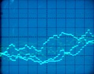
I measured a 1 KHz -60dB signal at the DAC output (NOS, no filtering). This is the "end result" note that it also contains interference due to a created ground loop as both SD-player and scope were mains powered and EMI.
The vertical setting equals 1mV / div (probe set to 1:1) so at -60dB I get approx. 2mVpp out of my SD-player. Full output (0dB) equals 2Vpp, so signal amplitude is approx. 1000 times lower. This means that the measured -60dB sine wave consists of approx. 65536 / 1000 = 65 steps or 6 bits.
I also added measurement of music reproduced by the SD-player. The signal transients between samples are almost invisible as jitter levels at the DAC output are extremely low (<40ps rms) and bandwidth is larger than 30 MHz. This in turn is required for accurately reproducing sample pulse energy and achieving high dynamic resolution.
The actual "smoothing" of the signal is done at the speakers (passive crossover filters and speaker mechanical properties) at the end of the signal path. This prevents divergence.
The connected audio equipment (volume control, power amp and speaker passive crossovers) are designed to remain stable over this large bandwidth.
Are you also implying that a low noise output can be obtained via maximum filtering before the regulator?
The regulator performs better when running on a clean (unstabilized) power supply. Interference dumped into a voltage regulator (polluted input voltage) will disrupt regulator feedback loop and degrade regulator performance. That's why I used maximum filtering before the regulator.
Like I mentioned, the regulator it self will also produce noise, but this is no longer mixed with interference from the input voltage. This regulator noise needs to be filtered too. One way to accomplish this is using large capacitors at the regulator output.
In this case, wouldn’t a double linear regulator in series on top of your LC filters helps a lot more?
Each linear regulator produces noise, cascading two of these means two noise sources that need to be filtered. It also means cascading two feedback loops, creating unwanted inter-actions between both feedback loops, increasing response time.
Also, I have noticed that you are using a film capacitor after the linear regulator, isn’t it going to cause the linear regulator to oscillate (according to JLH experiment (& many others) because of the capacitor's impedance needed to stablise)?
This was an experiment, I used 1206 size PPS caps with very low inductance. Performance appears to be roughly comparable with NPO caps. The low voltage rating of these caps (16V) are a problem. I now use Kemet 1uF 1206 size 25 or 50V X7R decoupling caps.
Did you happen to measure the output noise level, line regulation, PSRR into your ICs, eg. 1541A? If so, will it be possible to share with us the result?
Noise levels on TDA1541A power supplies are beyond the measuring capabilities of my measuring instruments. Other problem is screening both, device under test and measuring instrument from EMI.
I measured a 1 KHz -60dB signal at the DAC output (NOS, no filtering). This is the "end result" note that it also contains interference due to a created ground loop as both SD-player and scope were mains powered and EMI.
The vertical setting equals 1mV / div (probe set to 1:1) so at -60dB I get approx. 2mVpp out of my SD-player. Full output (0dB) equals 2Vpp, so signal amplitude is approx. 1000 times lower. This means that the measured -60dB sine wave consists of approx. 65536 / 1000 = 65 steps or 6 bits.
I also added measurement of music reproduced by the SD-player. The signal transients between samples are almost invisible as jitter levels at the DAC output are extremely low (<40ps rms) and bandwidth is larger than 30 MHz. This in turn is required for accurately reproducing sample pulse energy and achieving high dynamic resolution.
The actual "smoothing" of the signal is done at the speakers (passive crossover filters and speaker mechanical properties) at the end of the signal path. This prevents divergence.
The connected audio equipment (volume control, power amp and speaker passive crossovers) are designed to remain stable over this large bandwidth.
Attachments
Thanks again for sharing your insights.
Allow me to touch again on the topic of NOS. From your DAC output (E1~E4), I don’t see any filter or circuitry to reduce/eliminate unnecessary harmonic components unless you had left it out. I understand that a LPF(at least) is somehow needed to reduce any intermodulation distortion (let alone side band component).
From a patent shown here: Analog filter for digital audio system and audio amplifier for using the same - Patent 6721427 , it explains that:
The output signal contains a basic frequency component up to a frequency of 20khz as well as upper and lower side band components of the integral multiples of the sampling frequency Fs. …….. If these unnecessary components are reproduced by a speaker, cross modulation distortion may occur.
I believe due to the above, it’s an inherent problem of NOS thus leading some of the listener to hear some sort of distortions.
Do you believe in these type of filters are not needed at all in your experience? Is it possible that you share with me your experience or belief or knowledge on your decision even If you don’t believe some sort of filter is needed?
Meanwhile, correct me if I am wrong. I guess that your speakers and passive crossover might have already implemented some of that preventive/ elimination functionality in terms of sideband and cross modulation freq components. Is this how you solve the problem, if not did you do something after E1~E4 to resolve these?
PS: I want to know NOS is the way to go but how, using engineering terms.
double regulation
Hi ECD, just one question;
I had the oportunity of observing 3 pcb from the AMR CD77. Let me explain, an owner has this incredible CD player, (I've heard it) but, there were a storm and the CD player and others things burned. Then, the importer of Spain, wich one I know, gave me 3 pcbs (uau¡¡):
1-servo+D/A
2-1st supply (general one)
3-one channel output
I've saw that there is one pre-regulation, (discrete), and, on the servo bd, there is more regulations, like TL431, and so on. My question is that if you believe, that even with a well designed supply, the second regulation isn't necessary.
Best regards,
Hi fff0,
My objective is to keep the signal path as simple and straight-forward as possible.
Let's follow the signal in the ISD player.
DAC current output passes a single JFET current buffer and runs through the 500R passive I/V resistor into +5V. By doing so, all bit currents flow into +5V.
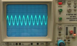
The voltage across the 500R passive I/V resistor is buffered by a discrete JFET unity gain buffer. The output at the buffer has large bandwidth (oscillograms posted earlier).
Next a hybrid coupling cap with DC compensation circuit is used to put the coupling cap in a "sweet spot" where distortion is lowest. This signal then enters a frequency compensated 10K motorized ALPS pot (low noise conductive plastic film).
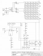
Signal is then fed into a balanced FET bridge power amp that remains stable up to at least 10 Mhz. I added a concept schematic of this power amp.
Interlinks are made using RF litz wire.
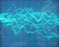
The bridge power amp is connected to the speakers using RF litz wire (8mm diameter). I added an oscillogram of the power amp output signal.
The sonic resonator passive filters are designed to handle large bandwidth input signals. There are 4 main filter parts, two multi-segmented honeycomb air chokes and two hybrid caps that have an extra PCB bypass cap. Two speakers, a bass-mid chassis and a tweeter are driven by this passive filter.
The signal on the woofer looks analogue when measuring it with the scope. This is caused by the passive xover filter. In other words, no visible steps, just a smooth signal.
The signal on the tweeter has step shape, but the tweeter starts to roll-off at approx. 25 KHz, removing RF energy by speaker mechanical limitations (RF converted to heat / losses).
Finally the human auditory system performs required brickwall filtering on a signal that's already band limited to approx. 30 KHz by the tweeter.
This method places the filtering at the end of the signal path instead of after the DAC chip. It uses given speaker properties that already provide band limiting starting at approx. 25 KHz.
Allow me to touch again on the topic of NOS. From your DAC output (E1~E4), I don’t see any filter or circuitry to reduce/eliminate unnecessary harmonic components unless you had left it out. I understand that a LPF(at least) is somehow needed to reduce any intermodulation distortion (let alone side band component).....
My objective is to keep the signal path as simple and straight-forward as possible.
Let's follow the signal in the ISD player.
DAC current output passes a single JFET current buffer and runs through the 500R passive I/V resistor into +5V. By doing so, all bit currents flow into +5V.
The voltage across the 500R passive I/V resistor is buffered by a discrete JFET unity gain buffer. The output at the buffer has large bandwidth (oscillograms posted earlier).
Next a hybrid coupling cap with DC compensation circuit is used to put the coupling cap in a "sweet spot" where distortion is lowest. This signal then enters a frequency compensated 10K motorized ALPS pot (low noise conductive plastic film).
Signal is then fed into a balanced FET bridge power amp that remains stable up to at least 10 Mhz. I added a concept schematic of this power amp.
Interlinks are made using RF litz wire.
The bridge power amp is connected to the speakers using RF litz wire (8mm diameter). I added an oscillogram of the power amp output signal.
The sonic resonator passive filters are designed to handle large bandwidth input signals. There are 4 main filter parts, two multi-segmented honeycomb air chokes and two hybrid caps that have an extra PCB bypass cap. Two speakers, a bass-mid chassis and a tweeter are driven by this passive filter.
The signal on the woofer looks analogue when measuring it with the scope. This is caused by the passive xover filter. In other words, no visible steps, just a smooth signal.
The signal on the tweeter has step shape, but the tweeter starts to roll-off at approx. 25 KHz, removing RF energy by speaker mechanical limitations (RF converted to heat / losses).
Finally the human auditory system performs required brickwall filtering on a signal that's already band limited to approx. 30 KHz by the tweeter.
This method places the filtering at the end of the signal path instead of after the DAC chip. It uses given speaker properties that already provide band limiting starting at approx. 25 KHz.
Attachments
Last edited:
I also added measurement of music reproduced by the SD-player. The signal transients between samples are almost invisible as jitter levels at the DAC output are extremely low (<40ps rms) and bandwidth is larger than 30 MHz. This in turn is required for accurately reproducing sample pulse energy and achieving high dynamic resolution.
The resolution in time domain in your oszillogram is very small, if it was higher, one could easily see the settling time of the DAC. Where do you expect to see jitter in such an ultra low resolution measurement, how many samples on the scope screen, I did not count them ?
But that is not the point, just a notice.
The bridge power amp is connected to the speakers using RF litz wire (8mm diameter). I added an oscillogram of the power amp output signal.
Still the same very low resolution in the oscillogram, but now one can easily notice settling time.
It seems you have unintentionally created a situation where the power amp acts as substitute of what is usually found in DACs: the active I/V stage which badly affects settling time of the DAC, be there NFB or not.
Look at your pictures, obviously the power amp can not follow the short rise time of the DAC chip.
Another notice:
The tweeter provides hf rolloff, but far from the required steepness.
Use google to find out that despite ultrasound can not be heard directly, it causes audible intermodulation distortion ( difference tones ) inside the ear.
Last edited:
Hi EC designer,
Have you ever tried a sin(x)/x filter ? It seems according to this user that a sin(x)/x filter is important, http://www.diyaudio.com/forums/digi...sign-sinx-x-filter-tda1541a-9.html#post112735 .
If not, may I know whats your rationale?
Have you ever tried a sin(x)/x filter ? It seems according to this user that a sin(x)/x filter is important, http://www.diyaudio.com/forums/digi...sign-sinx-x-filter-tda1541a-9.html#post112735 .
If not, may I know whats your rationale?
I made a test CD that has one track 0 dB 22.05 kHz square wave (alternating 0000 and FFFF samples). I got exactly 0 dB 22.05 kHz squre wave during playback on a NOS DAC. So where is the sin(x)/x rolloff? Perhaps I have to try with pink noise recording and an FFT analyzer, which I haven't done yet.
Hi fff0
I tried passive circuits that provide certain amount of trebles boost. I removed them shortly after as I didn't like the sound at all, it didn't sound natural and caused listening fatigue.
When applying "mild" analogue filtering after the DAC, higher frequencies are sine wave shaped The filters also introduce phase distortion.
Without any filtering after the DAC these higher frequencies have square wave shape. If I am correct square wave shape has form factor of 1 and sine wave shape has form factor of 0.707.
Measurements of AC magnitude : BASIC AC THEORY
This means that without "mild" filtering I end up with more power for trebles at the tweeter, and thus don't necessarily need a trebles booster circuit.
Have you ever tried a sin(x)/x filter ? It seems according to this user that a sin(x)/x filter is important
I tried passive circuits that provide certain amount of trebles boost. I removed them shortly after as I didn't like the sound at all, it didn't sound natural and caused listening fatigue.
When applying "mild" analogue filtering after the DAC, higher frequencies are sine wave shaped The filters also introduce phase distortion.
Without any filtering after the DAC these higher frequencies have square wave shape. If I am correct square wave shape has form factor of 1 and sine wave shape has form factor of 0.707.
Measurements of AC magnitude : BASIC AC THEORY
This means that without "mild" filtering I end up with more power for trebles at the tweeter, and thus don't necessarily need a trebles booster circuit.
I tried passive circuits that provide certain amount of trebles boost. I removed them shortly after as I didn't like the sound at all, it didn't sound natural and caused listening fatigue.
I have quite the opposite impression.
Treble rolloff results in a sound that is lacking transparency.
If a linear freq. resp. causes listening fatigue, then the problem is elsewhere in the audio chain.
When applying "mild" analogue filtering after the DAC, higher frequencies are sine wave shaped The filters also introduce phase distortion.
Unfiltered doesn't sound homogenous.
If I am correct square wave shape has form factor of 1 and sine wave shape has form factor of 0.707.
This means that without "mild" filtering I end up with more power for trebles at the tweeter, and thus don't necessarily need a trebles booster circuit.
but:
The signal on the tweeter has step shape, but the tweeter starts to roll-off at approx. 25 KHz, removing RF energy by speaker mechanical limitations (RF converted to heat / losses).
Finally the human auditory system performs required brickwall filtering on a signal that's already band limited to approx. 30 KHz by the tweeter.
Very interesting:
Where is your extra power for trebles gone ?
Transformed into thermal energy heating up your ear and your speakers.
Last edited:
- Home
- Source & Line
- Digital Line Level
- Building the ultimate NOS DAC using TDA1541A