extreme low jitter 11.2896 MHz masterclock was needed, I constructed a master clock with discrete components that runs on multiple 11.2896 MHz crystals, and uses an external 3V alkaline battery reference voltage (oscillator only draws 150nA, so the battery will last very long).
Hi EC
I wonder what noise floor can you get from the 11.2896MHz oscillator with such low current
-ecdesigns- said:
Meanwhile I improved the BCK attenuator / jitter reduction circuit, only few parts required.
Great news dear EC, maybe you can detail a little bit the new parts you have used for this since i'm at the point doing this job in a cd-player and any good advice from you is more than welcome.Thanks !
Hi soundcheck,
Just a test, set volume control to a level where sound is barely audible, then walk over to one of the speakers and listen. Is the sound crystal clear, revealing every single detail, and is hum / noise completely, and I mean completely inaudible now?
If yes, you can do without the described volume control.
When you do some practical measurements (at the speaker terminals), resolution is more like 12 ... 16 bits at maximum volume setting. The S/N ratio required for true 24-bit resolution simply cannot be maintained in a conventional audio set, resolution is already lost when the signal leaves the DAC PCB (provided the DAC PCB properties even enabled achieving true 24-bit resolution).
Example, your power amp produces approx. 7 watts rms in 8 Ohms (average volume setting). This translates to approx. 21Vpp at the speaker terminals. At 24 bit resolution, LSB change equals 21 / 2^24 = 1.25uVpp. You won't even be able to measure this with a plain oscilloscope set at maximum sensitivity using a 1:1 probe.
This is AFTER amplification in the power amp (usually 50 ... 100x), meaning that the same 1 LSB change at the power amp input represents 12.5 ... 25nV. This is AFTER the signal passed interlinks (pre-amp) and volume control.
Perhaps this illustrates the problem a bit better.
Same example with 16 bit resolution, 21 / 2^16 = 0.32mV, this is just barely measurable with a plain oscilloscope and a 1:1 probe. LSB change at the power amp input equals 3.2uV ... 6.4uV, even this is almost impossible to achieve considering the signal path.
Now the same with max. volume setting, 70 watts rms in 8 Ohms. This translates to approx. 67Vpp and a LSB change (16 bits) of 67 / 2^16 = 1mV. At the amplifier input (50x gain like with my amp), it results in 204uVpp LSB change and 1.34Vpp at the DAC output. Even the 240uVpp is already problematic, and requires very careful design and a clean mains voltage.
Yep, recently had my mains voltage tested in all rooms (expected too high interference levels @ 1 KHz ... 10 MHz). Well, average reading should have been around 25 GS units (acceptable), at my place the meter went off-the-scale (>1999 Gs units) and was finally damaged (overloaded). Time for some action.
After installing 15 filters at strategic points (and repairing the meter that appeared to have a blown 10nF multilayer cap), readout dropped to around 30 ... 40 GS units in every room.
The filters appear to be 15uF caps with a 47K bleeder resistor, and perhaps some other parts.
Here is the website of the manufacturer:
http://www.stetzerelectric.com/filters/
Also have a look under "Graham Stetzer research"
Bottom line is that mains voltage is pretty polluted nowadays and this will only get worse. This can be easily verified and quantified by measurements. So perhaps it's time for battery power supplies.
Batteries have relative low noise, and most important, offer a true floating power supply / reference voltage, and don't contain pollution like present on the mains.
My favorites are plain alkaline batteries and lead acid batteries.
The SD-player is designed to run on a single 5V source (approx. 250mA), so it can run on a battery power supply. Meaning both digital audio source and DAC can run on a clean floating battery power supply, and when using this setup, ground-loops with connected equipment can be completely avoided.
I for sure would never put powerresitors in the chain.
Just a test, set volume control to a level where sound is barely audible, then walk over to one of the speakers and listen. Is the sound crystal clear, revealing every single detail, and is hum / noise completely, and I mean completely inaudible now?
If yes, you can do without the described volume control.
I do understand that 24bit is a problem for your setup
When you do some practical measurements (at the speaker terminals), resolution is more like 12 ... 16 bits at maximum volume setting. The S/N ratio required for true 24-bit resolution simply cannot be maintained in a conventional audio set, resolution is already lost when the signal leaves the DAC PCB (provided the DAC PCB properties even enabled achieving true 24-bit resolution).
Example, your power amp produces approx. 7 watts rms in 8 Ohms (average volume setting). This translates to approx. 21Vpp at the speaker terminals. At 24 bit resolution, LSB change equals 21 / 2^24 = 1.25uVpp. You won't even be able to measure this with a plain oscilloscope set at maximum sensitivity using a 1:1 probe.
This is AFTER amplification in the power amp (usually 50 ... 100x), meaning that the same 1 LSB change at the power amp input represents 12.5 ... 25nV. This is AFTER the signal passed interlinks (pre-amp) and volume control.
Perhaps this illustrates the problem a bit better.
Same example with 16 bit resolution, 21 / 2^16 = 0.32mV, this is just barely measurable with a plain oscilloscope and a 1:1 probe. LSB change at the power amp input equals 3.2uV ... 6.4uV, even this is almost impossible to achieve considering the signal path.
Now the same with max. volume setting, 70 watts rms in 8 Ohms. This translates to approx. 67Vpp and a LSB change (16 bits) of 67 / 2^16 = 1mV. At the amplifier input (50x gain like with my amp), it results in 204uVpp LSB change and 1.34Vpp at the DAC output. Even the 240uVpp is already problematic, and requires very careful design and a clean mains voltage.
Interesting to see that you start working with batteries.
Yep, recently had my mains voltage tested in all rooms (expected too high interference levels @ 1 KHz ... 10 MHz). Well, average reading should have been around 25 GS units (acceptable), at my place the meter went off-the-scale (>1999 Gs units) and was finally damaged (overloaded). Time for some action.
After installing 15 filters at strategic points (and repairing the meter that appeared to have a blown 10nF multilayer cap), readout dropped to around 30 ... 40 GS units in every room.
The filters appear to be 15uF caps with a 47K bleeder resistor, and perhaps some other parts.
Here is the website of the manufacturer:
http://www.stetzerelectric.com/filters/
Also have a look under "Graham Stetzer research"
Bottom line is that mains voltage is pretty polluted nowadays and this will only get worse. This can be easily verified and quantified by measurements. So perhaps it's time for battery power supplies.
Batteries have relative low noise, and most important, offer a true floating power supply / reference voltage, and don't contain pollution like present on the mains.
My favorites are plain alkaline batteries and lead acid batteries.
The SD-player is designed to run on a single 5V source (approx. 250mA), so it can run on a battery power supply. Meaning both digital audio source and DAC can run on a clean floating battery power supply, and when using this setup, ground-loops with connected equipment can be completely avoided.
Hi yygomez,
The oscillator runs on 5V (approx. 10mA), the 1.5V is used as reference voltage to bias the JFETs in the master clock.
The oscillator is basically a buffer with a phase shifter and a crystal filter in the feedback loop. This results in a pure, very low distortion 5Vpp sine wave at the amplifier input.
I already constructed a prototype with 8 crystals in the feedback loop (very difficult to tune), I now use simpler versions with 2 or 3 crystals that are less critical and more easy to build.
I picked the signal from the JFET input, using a second Buffer circuit.
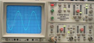
I attached an oscillogram of a 2-crystal version running on a dirty 5V power supply and using a 1.5V alkaline reference voltage. I included the scope in the picture to verify settings. I used a 1:10 probe, and time base X10 setting. Frequency equals 11.2896 MHz.
The sine wave can be used to trigger a suitable high-speed comparator with high input impedance and low input capacity. but amplitude is also high enough to directly trigger connected loads (after unity gain buffering).
I wonder what noise floor can you get from the 11.2896MHz oscillator with such low current
The oscillator runs on 5V (approx. 10mA), the 1.5V is used as reference voltage to bias the JFETs in the master clock.
The oscillator is basically a buffer with a phase shifter and a crystal filter in the feedback loop. This results in a pure, very low distortion 5Vpp sine wave at the amplifier input.
I already constructed a prototype with 8 crystals in the feedback loop (very difficult to tune), I now use simpler versions with 2 or 3 crystals that are less critical and more easy to build.
I picked the signal from the JFET input, using a second Buffer circuit.
I attached an oscillogram of a 2-crystal version running on a dirty 5V power supply and using a 1.5V alkaline reference voltage. I included the scope in the picture to verify settings. I used a 1:10 probe, and time base X10 setting. Frequency equals 11.2896 MHz.
The sine wave can be used to trigger a suitable high-speed comparator with high input impedance and low input capacity. but amplitude is also high enough to directly trigger connected loads (after unity gain buffering).
Attachments
Perhaps you remember: I am using batteries fon almost everything for quite a while - my amp also runs on batteries ( This way I can even run my amp DC coupled - which makes a huge difference).
Strictly seperated the analog and digital supply. I get along with 12V throughout the chain.
(Which requires a high SPL speaker of course if you want to avoid DC/DC converters).
The great thing I am mainly talking about "The First Watt" only to stay in Nelson Pass terms. This gives me much more flexibility then anything else. I don't enter "distoration critical" phases in any situation. I run low gain amplification etc. That's IMO more worth than anything else.
I selected one of the Northstar batteries ( I don't know any better choice) since there was no other giving me low ESR of 2mR.
I guess there are not very many PS supplies which can compete with this. These batteries are quite expensive nowadays. People will think twice to spend 250$ for one battery.
The 24bit thing refers to volume control on my PC without impacting the signal a lot. I received some feedback from a dutch friend last week, that he finally took out his passive control, to connect the DAC rigth to the amp. He won't switch back. Me neither.
Cheers
The oscillator runs on 5V (approx. 10mA), the 1.5V is used as reference voltage to bias the JFETs in the master clock. The oscillator is basically a buffer with a phase shifter and a crystal filter in the feedback loop. This results in a pure, very low distortion 5Vpp sine wave at the amplifier input. I already constructed a prototype with 8 crystals in the feedback loop (very difficult to tune), I now use simpler versions with 2 or 3 crystals that are less critical and more easy to build. I picked the signal from the JFET input, using a second Buffer circuit. I attached an oscillogram of a 2-crystal version running on a dirty 5V power supply and using a 1.5V alkaline reference voltage. I included the scope in the picture to verify settings. I used a 1:10 probe, and time base X10 setting. Frequency equals 11.2896 MHz. The sine wave can be used to trigger a suitable high-speed comparator with high input impedance and low input capacity. but amplitude is also high enough to directly trigger connected loads (after unity gain buffering).
EC
Thanks for the answer.
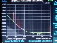
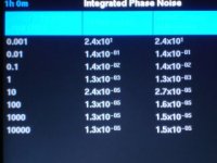
If you are interested I can help you to measure the Phase Noise of the master clock/Buffer, I have access to a Symmetricon 5021A Phase noise test set, In such way you can fully characterize the jitter of your master clock.
Attached some screen pictures:
Attachments
Hi EC,
Thanks for your reply (post #2818).
Glad you are making progress
I have learnt to fear your long silences
Just when I was prepearing myself to build a "one box solution" D1M (or D4M or D16M) with trans-impedance circuit and variable I/V resistor as volume selector, with class A power buffer (whose schematic you would kindly care to provide ) you came up with this other possibility of power resistor to attenuate musical signal pre-speaker
Frankly the power resistor in series is not very practical to me, safe on my full-range speakers, probably. Isn't it better to change I/V resistor as was your first idea?
About your SD-card player, my canines are already this long hearing about it Won't you at least show some picks to calm our hunger?
Cheers,
M
Off topic post scriptum: for those interested in classical music from the past, please check out http://www.europarchive.org/
Thanks for your reply (post #2818).
Glad you are making progress
I have learnt to fear your long silences
-ecdesigns- said:Hi maxlorenz,
Meanwhile I improved the BCK attenuator / jitter reduction circuit, only few parts required.
SD-player design is almost completed. First an extreme low jitter 11.2896 MHz masterclock was needed, I constructed a master clock with discrete components that runs on multiple 11.2896 MHz crystals, and uses an external 3V alkaline battery reference voltage (oscillator only draws 150nA, so the battery will last very long). During testing it became clear that the battery reference was required to get best transparency and focus. I didn't succeed in constructing a suitable mains-powered reference voltage.
The SD-card player sound quality (while running on this new master clock) is simply stunning, SPDIF is absolutely no match for this, no matter what jitter blocker is used in the DAC, even slaving the transport won't provide results like this.
With this clean digital audio source, I was able to easily determine the best performing I/V converter, as the sound is highly transparent, revealing everything.
Well, the best performer (to my surprise) is plain passive I/V conversion with resistors, ignoring TDA1543 output compliance. I use a single TDA1543 DAC chip, 2 x 680 Ohm I/V resistors connected to a 3V alkaline battery reference voltage. This gives me 2 x 1.56Vpp without using the Vref pin. I did try connecting both a resistor and a CCS from Vref to GND in order to shift bias current to obtain sine wave output with very low distortion (at 1.56Vpp). But anything connected to Vref greatly degraded sound quality, So that's why I used a 3V reference voltage instead.
The 1.56Vpp output voltage amplitude is plenty to drive my MOSFET power amp that has a gain of 50, close to clipping. The power amp is fully DC-coupled, and I only use 2 x 1uF coupling caps in the entire signal path. Power amp input impedance is approx. 100 K Ohm. I connected the DAC output straight to my power amp (no conventional volume control anymore).
Volume was now controlled by variable power resistors in series with the speakers.
Even at whispering low volume settings, sound is crystal clear and highly detailed (maximum resolution regardless of volume setting).
Hum and noise are totally inaudible, even when listening very close to the speaker.
I plan to use digitally controlled power attenuators (relays and power resistors) that are placed as close to the speakers as possible, this also results in far less critical speaker interlinks. Both L and R attenuator modules are driven by a central control unit with remote control.
Just when I was prepearing myself to build a "one box solution" D1M (or D4M or D16M) with trans-impedance circuit and variable I/V resistor as volume selector, with class A power buffer (whose schematic you would kindly care to provide
) you came up with this other possibility of power resistor to attenuate musical signal pre-speaker Frankly the power resistor in series is not very practical to me, safe on my full-range speakers, probably. Isn't it better to change I/V resistor as was your first idea?
About your SD-card player, my canines are already this long hearing about it
Won't you at least show some picks to calm our hunger?Cheers,
M
Off topic post scriptum: for those interested in classical music from the past, please check out http://www.europarchive.org/
Hi maxlorenz,
class A power buffer (whose schematic you would kindly care to provide). I could post a schematic.
The problem with this configuration is that the buffer (cross-over) distortion, and noise / hum is dumped on the speakers without attenuation. With the new volume control, this distortion (and noise / hum) is attenuated, and signal amplitude is always maximum. This lifts the signal well above the noise floor, and provides much better clarity at the volume settings that are most often used.
you came up with this other possibility of power resistor to attenuate musical signal pre-speaker
Yes, the concept is driving the power amp without pre-amp or volume control. This skips a lot of problems with impedance matching and too low signal levels (poor S/N ratio).
The amplifier should provide an signal that doesn't clip at 0dB. Now variable power resistors are placed in series with the speaker. Lowest volume setting is achieved by say 5 K Ohm in series with the speaker, and highest when short-circuiting the resistor. Since the attenuators are best placed close to each speaker, I plan to use a stepped volume control consisting of suitable relays, and some power resistors. Both attenuators are hooked-up to a central control unit that drives the relays of both channels.
Other possibility would be combining both resistive power attenuators and amplifier gain.
The result is unparalleled resolution and clarity at low to medium volume settings. Due to the absence of pre-amp, volume control and an extra set of interlinks, the problems introduced by these parts are now non existent.
Frankly the power resistor in series is not very practical to me, safe on my full-range speakers, probably. Isn't it better to change I/V resistor as was your first idea?
Conventional volume controls may be efficient and practical, they do not provide best resolution and clarity for sure. Just think of this, the DAC (or other device) outputs a 2Vpp signal. This signal is then attenuated to 100mV or so (average volume setting), pushing the signal deep into the noise floor. Next the whole mess is (pre) amplified 50 ... 100 times, and is then dumped on the speakers without attenuation. Logically speaking this is not a very bright idea. When directly driving the power amp (nothing between DAC and power amp), full signal amplitude is used, all the time, signal isn't attenuated nor pushed in the noise floor, achieving best resolution. The series resistor also provides an almost pure resistive load at moderate volume settings, this usually enables lower distortion in the power amp. The sonic impression is that of a class A amplifier.
About your SD-card player, my canines are already this long hearing about it Won't you at least show some picks to calm our hunger?
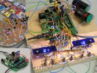
I attached a picture I made yesterday (my excuses for the messy prototype set-up). The small picture (top-left) shows some of the many SD-cards we tested, the one (bottom-left) shows the player during software development. The card that failed the test was a Verbatim 2Gb card with no speed rating.
The idea is to construct a low-cost player (including DAC chip and the new master clock with 2 or 3 crystals). The whole thing should easily fit on a euro-sized PCB. It runs on a 8 ... 12V external power supply, so one can choose between battery or mains power supply. I am currently running the prototype on a cheap mains adapter, and sound quality easily exceeds my best TDA1541A-based DACs with SPDIF or direct I2S. The prototype setup is far from optimal, so this is basically worst-case set-up.
When this player is completed, I plan to design an ultimate version with the TDA1541A, a 12-crystal super-master clock, and very high speed (4GHz) ECL logic for clock distribution. This DAC will probably have a tube output, perhaps using the new JJ electronics 6386 LGP.
The left blue LED display indicates the CD number (1 ... 99) and CD shuffle mode (decimal point comes on). The right display indicates track number of selected CD (1 ... 99) and track shuffle mode. There will be an option for battery-powered mode (LED displays dim few seconds after no key has been detected).
There will be 5 keys, two for CD - / + and 2 x stop, one for play / pause, and two for track - / + and 2 x stop. The prototype still has the extra stop key.
The SD / SDHC-card size can vary between 1 and 32 Gb. Both 4Gb and 8Gb cards are most interesting at the moment, micro-SD cards can be used as well (requires adapter). In order to get sufficient throughput and acceptable latency, cards with speed rating of 2 and higher should be used (most cheap cards already have speed rating 6 now).
Just to give an idea of what's possible, I managed to put 13 CDs (WAV format) on one single 8Gb card that cost around eur 14. The 4Gb cards can hold up to 6 CDs.
The player responds fast when pushing the keys, there is a short delay (1 second) when swapping the SD card, as the controller has to scan the entire SD / SDHC card file structure. I really like the snappy response and ease of use. But most important is the much better sound quality compared to other digital audio sources I tested before. Key factors are the single master clock and the single master clock jitter spectrum, the low bit clock frequency, and the continuous data stream (not interrupted by 16 un-used bits between samples).
The WAV files can be written to the memory card using a cheap card reader / writer.
The player outputs I2S, 32 bits/frame (16 bits for left channel, directly followed by 16 bits for right channel). Sample frequency is fixed @ 44.1 KHz, and bit clock equals 44,100 * 32 = 1.4112 MHz. The low bit clock frequency provides lowest possible ground bounce with time-multiplex mode, this alone makes this player better than any SPDIF source that outputs 2.8224 MHz bit clock.
The master clock is on the left (disc), this one has 3 crystals in the feedback loop. The final version will be placed in a screened box. The batteries for bias voltages are not visible on this picture. I use 3V (alkaline penlight batteries) for both master clock (voltage divider > 1.5V), and TDA1543 reference. These batteries last up to 1000 hours of continuous operation (depending on battery capacity). The TDA1543 reference draws maximum current (2.3mA).
The picture basically shows the complete player, the grey wire is directly connected to my power amp. The coupling capacitors appear to be far less critical now, and even miniature 1uF / 50V WIMA caps sound excellent.
There is more information about this player on my other thread:
http://www.diyaudio.com/forums/showthread.php?threadid=140538
Attachments
Conventional volume controls may be efficient and practical, they do not provide best
Hi EC,
May be would be better to insert a "π" or a "T" power attenuator in order to preserve the output impedance and damping factor, what do you think?
Cheers,
Conventional volume controls may be efficient and practical, they do not provide best resolution and clarity for sure. Just think of this, the DAC (or other device) outputs a 2Vpp signal. This signal is then attenuated to 100mV or so (average volume setting), pushing the signal deep into the noise floor. Next the whole mess is (pre) amplified 50 ... 100 times, and is then dumped on the speakers without attenuation. Logically speaking this is not a very bright idea. When directly driving the power amp (nothing between DAC and power amp), full signal amplitude is used, all the time, signal isn't attenuated nor pushed in the noise floor, achieving best resolution. The series resistor also provides an almost pure resistive load at moderate volume settings, this usually enables lower distortion in the power amp. The sonic impression is that of a class A amplifier.
Hi EC,
May be would be better to insert a "π" or a "T" power attenuator in order to preserve the output impedance and damping factor, what do you think?
Cheers,
-ecdesigns- said:When you do some practical measurements (at the speaker terminals), resolution is more like 12 ... 16 bits at maximum volume setting. The S/N ratio required for true 24-bit resolution simply cannot be maintained in a conventional audio set, resolution is already lost when the signal leaves the DAC PCB (provided the DAC PCB properties even enabled achieving true 24-bit resolution).
Example, your power amp produces approx. 7 watts rms in 8 Ohms (average volume setting). This translates to approx. 21Vpp at the speaker terminals. At 24 bit resolution, LSB change equals 21 / 2^24 = 1.25uVpp. You won't even be able to measure this with a plain oscilloscope set at maximum sensitivity using a 1:1 probe.
This is AFTER amplification in the power amp (usually 50 ... 100x), meaning that the same 1 LSB change at the power amp input represents 12.5 ... 25nV. This is AFTER the signal passed interlinks (pre-amp) and volume control.
Perhaps this illustrates the problem a bit better.
Same example with 16 bit resolution, 21 / 2^16 = 0.32mV, this is just barely measurable with a plain oscilloscope and a 1:1 probe. LSB change at the power amp input equals 3.2uV ... 6.4uV, even this is almost impossible to achieve considering the signal path.
Now the same with max. volume setting, 70 watts rms in 8 Ohms. This translates to approx. 67Vpp and a LSB change (16 bits) of 67 / 2^16 = 1mV. At the amplifier input (50x gain like with my amp), it results in 204uVpp LSB change and 1.34Vpp at the DAC output. Even the 240uVpp is already problematic, and requires very careful design and a clean mains voltage.
I am slightly astonished, that nobody questions these statements, if they were correct, it would be a waste of time to make ad/da converters or music files with more than 16bits.
Here dynamic range and resolution have been mixed up.
Of course we can not hear the lower digital binary numbers, because they disappear into hiss or hum, but we certainly can hear the resolution, that means the difference between a number and the next higher one. If the resolution power of the system is good, this can certainly be heard, because it is above the noise floor. Let us do an analogy with decimal numbers:
Lets say our system is capable of 1000 different volumes, 1 to 1000, the resolution power is 1/1000.
Because of noise numbers 1 to 200 will disappear, we can just hear the numbers from 200 to 1000, but the resolution power is still there, is still 1/1000.
We can explain it in binary numbers as well:
010000000000000000000000
This is a 24 bit/digit binary number, its value is 6db below maximum, because it is shifted one digit to the right, no noise floor here of course! If we add 1, we have the resolution:
010000000000000000000001
If the system can differentiate this, it can sound probably more lifelike/ detailed.
regards
Andre
Thanks EC for your reply (post 2***)
class A power buffer (whose schematic you would kindly care to provide).
I could post a schematic. The problem with this configuration is that the buffer (cross-over) distortion, and noise / hum is dumped on the speakers without attenuation. With the new volume control, this distortion (and noise / hum) is attenuated, and signal amplitude is always maximum. This lifts the signal well above the noise floor, and provides much better clarity at the volume settings that are most often used.you came up with this other possibility of power resistor to attenuate musical signal pre-speaker
I planned to use a singled ended class A power buffer (to avoid crossover distortion) and a regulated supply (to avoid humm). I found Pavel Macura's "Mosfet Power Follower" as per the description on Elliot's site:
http://sound.westhost.com/project83.htm
the DAC (or other device) outputs a 2Vpp signal. This signal is then attenuated to 100mV or so (average volume setting), pushing the signal deep into the noise floor. Next the whole mess is (pre) amplified 50 ... 100 times, and is then dumped on the speakers without attenuation.
Yeah, it is weird...we should challenge common practice more often.
I could attenuate at the digital level, but I am not as smart as Soundcheck to do this without fear of lost of resolution...
I attached a picture I made yesterday (my excuses for the messy prototype set-up).
What do you say? I love messy prototypes
There is more information about this player on my other thread:
Oops! I totally missed that one...
Time to catch up...
Cheers,
M
Hi John,
The idea that you can simply add an attenuator between the amp and the speaker is very attractive BUT unfortunately, it runs into many problems - in short, the amplifier and speaker are a SYSTEM and work together because of the difficult and varying speaker parameters that change with driver impedance, power, freq, phase, transient response, compression, Xover, etc, plus the amps ability to control the back emf and avoid loading the neg feedback networks, output stage damping, etc, etc. Adding a FIXED value resistive attenuator network into the middle of this is a relatively simple thing (driver eq) but even this produces unexpected complications and so a full freq range, varyible load attenuator will introduce enormous difficulties (even with a reduced operating volume range), particularly with very high quality sound reproduction. Perhaps it would be better to use this higher voltage output from the DAC and adjust the gain of the amplifier for the required volume or perhaps a higher voltage attenuator with an output power buffer - a much simpler thing to do.
The idea that you can simply add an attenuator between the amp and the speaker is very attractive BUT unfortunately, it runs into many problems - in short, the amplifier and speaker are a SYSTEM and work together because of the difficult and varying speaker parameters that change with driver impedance, power, freq, phase, transient response, compression, Xover, etc, plus the amps ability to control the back emf and avoid loading the neg feedback networks, output stage damping, etc, etc. Adding a FIXED value resistive attenuator network into the middle of this is a relatively simple thing (driver eq) but even this produces unexpected complications and so a full freq range, varyible load attenuator will introduce enormous difficulties (even with a reduced operating volume range), particularly with very high quality sound reproduction. Perhaps it would be better to use this higher voltage output from the DAC and adjust the gain of the amplifier for the required volume or perhaps a higher voltage attenuator with an output power buffer - a much simpler thing to do.
Hi John,
I also wonder why you are doing this.
At low volumes, so high series resistor versus load, you will create a current source in stead of a voltage source.
We know that loudspeakers have very bumby impedance curves, hence we need voltage source. By driving current, your frequency response will follow the impedance curve, which happens to be highest at bass resonance frequency and the high frequencies.
basically you create a loudness effect at low volumes. Is that why is sounds so nice ?
On top, you listen to different frequency respons at every position of the volume controll
Unless you complete flatten the impedance curve (what can be done) this is no option imo
If this is done in your system, that is fine than, so in that case let this be a warning to others, not to implement it without any thought. It is not a general solution
If your fear is, that you amplify noise etcetera, why not put volume controll directly for the Power amplifier last stage (1x gain) ? In that case you fullfill your requirements as well. Of course you need a good power supply, but I have never had problems with that on the last stage introducing humm or noise (audible)
Hi rolls,
High resolution recordings are required (digital mixing) so these aren't a waste of time.
I am referring to digital audio playback only, and the practical limitations of audio sets at moderate volume settings.
This article might be interesting:
http://www.proavmagazine.com/industry-news.asp?sectionID=1765&articleID=596561
Seems 16 bits (93dB dynamic range) is plenty for a practical High-End digital audio playback system.
The dynamic range of an audio set at a given volume setting, and listening distance / position from the speakers can be tested with the Sheffield lab test CD "My Disc A2TB.
http://www.amazon.com/Sheffield-A2TB-Test-Disc-My/dp/B000V93NKY
I am slightly astonished, that nobody questions these statements, if they were correct, it would be a waste of time to make ad/da converters or music files with more than 16bits.
High resolution recordings are required (digital mixing) so these aren't a waste of time.
I am referring to digital audio playback only, and the practical limitations of audio sets at moderate volume settings.
This article might be interesting:
http://www.proavmagazine.com/industry-news.asp?sectionID=1765&articleID=596561
Seems 16 bits (93dB dynamic range) is plenty for a practical High-End digital audio playback system.
The dynamic range of an audio set at a given volume setting, and listening distance / position from the speakers can be tested with the Sheffield lab test CD "My Disc A2TB.
http://www.amazon.com/Sheffield-A2TB-Test-Disc-My/dp/B000V93NKY
-ecdesigns- said:Hi rolls,
High resolution recordings are required (digital mixing) so these aren't a waste of time.
I am referring to digital audio playback only, and the practical limitations of audio sets at moderate volume settings.
This article might be interesting:
http://www.proavmagazine.com/industry-news.asp?sectionID=1765&articleID=596561
Seems 16 bits (93dB dynamic range) is plenty for a practical High-End digital audio playback system.
The dynamic range of an audio set at a given volume setting, and listening distance / position from the speakers can be tested with the Sheffield lab test CD "My Disc A2TB.
http://www.amazon.com/Sheffield-A2TB-Test-Disc-My/dp/B000V93NKY
Hello John
You and the guy in the article still mix up dynamic range and resolution.
You can have a dynamic range of 93db only and still a resolution power of 24bit, it means that the steps are finer, one step is 1 divide by 2 to the power of 24.
In other words, the binary word is not zero when it "leaves" noise.
High resolution recordings are not made for mixing purpose only, you can download them from different sources. I agree that probably we will never have a system with a dynamic range of a complete range of 24bit numbers, 144db.


 Oh yes, I did !
Hi Bernhard,
Project is on target, the main objective is almost achieved. The design process is well documented on this thread. The preceding years were necessary to systematically locate bottlenecks in the design and eliminate them.
There is a practical result, and a conclusion.
The conclusion is that one of the major problems is the digital audio source. There will be no ultimate DAC without an ultimate digital audio source. I wasn't able to find a suitable digital audio source, so both my brother and I designed one from scratch.
The practical result is the SD-player.
I can't help it if you are puzzled, and yes the TDA1543 is capable of producing crystal clear sound, it's just a matter of design.
I attempted to explain why I did this, I can't help it if you can't understand.
After nearly two and a half years and 114 pages it's ended up with an overdriven crap TDA1543, rudely violating its voltage compliance.
Crystal clear sound.
I'm puzzled.
Project is on target, the main objective is almost achieved. The design process is well documented on this thread. The preceding years were necessary to systematically locate bottlenecks in the design and eliminate them.
There is a practical result, and a conclusion.
The conclusion is that one of the major problems is the digital audio source. There will be no ultimate DAC without an ultimate digital audio source. I wasn't able to find a suitable digital audio source, so both my brother and I designed one from scratch.
The practical result is the SD-player.
I can't help it if you are puzzled, and yes the TDA1543 is capable of producing crystal clear sound, it's just a matter of design.
I will be soon implementing the passive volume control on the output of my power amplifier
I attempted to explain why I did this, I can't help it if you can't understand.
- Home
- Source & Line
- Digital Line Level
- Building the ultimate NOS DAC using TDA1541A