mount the reverb spring in whatever position it was originally. they are made with the suspension springs in various positions to keep the tank suspended properly in one position only. i could explain how to modify the suspensions for various mounting positions, but i'd need one in front of me, and i don't have one in my parts collection. if you have good-to-excellent mechanical skills, it's not too hard to figure out.
Yes my friend google.... have seen variants, from tube to chip to transistors handleing the tank...
http://www.freeinfosociety.com/electronics/schempage.php?cat=1
You can also follow that link and find many schematics to pirate off...
http://www.freeinfosociety.com/electronics/schempage.php?cat=1
You can also follow that link and find many schematics to pirate off...
Here's the test jig I use for spring tanks:
http://geek.scorpiorising.ca/GeeK_ZonE/index.php?topic=3551
You can lose the 5751 and adapt it in")
Cheers!
http://geek.scorpiorising.ca/GeeK_ZonE/index.php?topic=3551
You can lose the 5751 and adapt it in
Cheers!
here's a breakdown of the part nimber system for reverb tanks:
Accutronics Reverb Tanks
Almost all the reverb tanks that one sees for sale are the Accutronics brand. They are made by:
Sound Enhancements, Inc.
185 Detroit St.
Cary, IL 60013
Although they make many models, the three types that are readily available are a limited number of their types 4, 8, and 9. The type 4 is 17" long and uses 2 long springs, each of which consists of two springs joined in the middle. Thus, Accutronics considers this model a 4-spring unit. This type was the original style selected by Leo Fender. The type 8 is 9" long and uses 3 springs. This type is most famous for its use by Marshall. The type 9 is 17" long and uses 3 long springs, each of which consists of two springs joined in the middle. Analogously, Accutronics considers this unit a 6-spring device. All Accutronics' part numbers consist of 7 characters as described below.
1st character: type 4, 8, or 9
2nd character: Input impedance @ 1kHz
Type | A B C D E F
4 | 8 ohms 150 ohms 200 ohms 250 ohms 600 ohms 1475 ohms
8 and 9 | 10 ohms 190 ohms 240 ohms 310 ohms 800 ohms 1925 ohms
3rd character: Output impedance @ 1 kHz
Type | A B C
4 | 500 ohms 2250 ohms 10000 ohms
8 and 9 | 600 ohms 2575 ohms 12000 ohms
4th character: Decay time
1 = short (1.2 to 2 sec)
2 = medium (1.75 to 3.0 sec)
3 = long (2.75 to 4 sec)
5th character: Connector arrangement
A = input grounded, output grounded
B = input grounded, output insulated
C = input insulated, output grounded
D = input insulated, output insulated
6th character: Locking device 1 = no lock
7th character: Mounting plane
A = horizontal,open side up
B = horizontal, open side down
C = vertical wall,long axis horizontal, connectors up
D = vertical wall, long axis horizontal, connectors down
E = vertical wall, long axis vertical, input up
F = vertical wall, long axis vertical, output up
The following table summarizes the above data for the most commonly available units:
PART NUMBER PRIMARY USER LENGTH NUMBER OF SPRINGS INPUT IMPEDANCE@ 1KhZ/DC
OUTPUT IMPEDANCE @ 1KhZ/dc
4AB3C1B Fender 17" 4 8ohms/.81ohms 2,250ohms/200ohms
4BB2C1B Acoustic/SLM/Ampeg 17" 4 150ohms/26ohms 2,250ohms/200ohms
4EB2C1B Peavey 17" 4 600ohms/58ohms 2,250ohms/200ohms
4FB3D1B Music Man General 17" 4 1475ohms/200ohms 2,250ohms/200ohms
9AB2C1B Fender/ Boogie 17" 6 10ohms/.81ohms 2575ohms/200ohms
9EB2C1B Peavey/General 17" 6 800/58ohms 2575ohms/200ohms
9FB2A1C General 17" 6 1,925/200ohms 2575ohms/200ohms
8AB2A1B Boogie 9" 3 10ohms/.81ohms 2575ohms/200ohms
8BB2A1B SLM 9" 3 190ohms/26ohms 2575ohms/200ohms
8DB2C1B Marshall 9" 3 310ohms/36ohms 2575ohms/200ohms
8EB2C1B Fender 9" 3 800ohms/58ohms 2575ohms/200ohms
if you know where the isolating springs go for each mounting position, you can change the mounting type (mounting plane). all you have to do is move the outside ends of the springs to the proper holes in the case.
More questions
Okay some more newbish questions since I was thinking of doing this as well and buying a line level reverb tank or two for my bedroom recording studio.
Are reverb tanks passive devices? That need to be followed by a pre-amp? And if so what would be the best way to do the impedance flow?
For instance my soundcard which I plan on bussing tracks to the reverb unit is the Mackie Onyx 400f. Output impedance is like this.
Mic Input:
2.4 kΩ balanced
Inst Input:
1 MΩ
Line:
20 kΩ balanced, 10 kΩ unbalanced
Output Impedance
Line:
100 Ω balanced
Now if it is passive should I have the input impeadance come as close as possible to the output impeadance of the line outs on the Onyx (150ohm or 200ohm)? And do the same for the output of the reverb tank and the inputs of the card (10k for line or 2.25k for mic input pre-amp).
a "line level" reverb tank should have the driver and preamp circuits included. the reverb tanks in previous posts are the basic spring units themselves with no drivers/preamps, just the metal box with springs and magnetics.
just running the outputs of the soundcard into a spring unit won't work well, as there's a huge amount of loss in the transducers and springs.
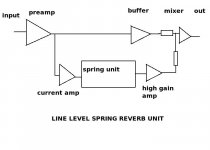
usually with a spring unit, you have a preamp and spring driver. at the input to the spring driver, the audio path splits int two paths "dry" (original signal) and "wet" (the reverb signal). the "dry" signal then goes directly to the output mixer/buffer. the "wet" signal is amplified to get the required drive current to the spring's input transducer. the transducer is like a small electromagnet that drives the steel spring with audio. the steel spring vibrates mechanically and acts as a delay line. that's why there are more than one spring with different coil pitches, one spring has more delay than the one next to it so the echoes from each spring arrive at different times. also, being springs, the signal echoes back and forth many times along the springs. at the output end, a second transducer magnetically picks up the vibration of the springs and turns it back into an audio signal, which is amplified by a high gain preamp stage and fed into the mixer/buffer to be mixed with the "dry" signal.
actually using a soundcard, i'm surprised you don't have a spring "emulator". some of the better modeled ones sound quite convincing, until you bump the side of the computer and no spring "crash" comes out......
just running the outputs of the soundcard into a spring unit won't work well, as there's a huge amount of loss in the transducers and springs.
usually with a spring unit, you have a preamp and spring driver. at the input to the spring driver, the audio path splits int two paths "dry" (original signal) and "wet" (the reverb signal). the "dry" signal then goes directly to the output mixer/buffer. the "wet" signal is amplified to get the required drive current to the spring's input transducer. the transducer is like a small electromagnet that drives the steel spring with audio. the steel spring vibrates mechanically and acts as a delay line. that's why there are more than one spring with different coil pitches, one spring has more delay than the one next to it so the echoes from each spring arrive at different times. also, being springs, the signal echoes back and forth many times along the springs. at the output end, a second transducer magnetically picks up the vibration of the springs and turns it back into an audio signal, which is amplified by a high gain preamp stage and fed into the mixer/buffer to be mixed with the "dry" signal.
actually using a soundcard, i'm surprised you don't have a spring "emulator". some of the better modeled ones sound quite convincing, until you bump the side of the computer and no spring "crash" comes out......
Yeah, I guess I am wondering if I can get around that by selecting the proper impedance and just using one of my mic pre-amps.
And realize this is for a multitrack so I don't need onboard blending or any of that. Just full reverb to be tracked and blended. No frills as little circuitry as possible.
And realize this is for a multitrack so I don't need onboard blending or any of that. Just full reverb to be tracked and blended. No frills as little circuitry as possible.
if you had one of the spring units with the 8 ohm input coil, you could concievably drive the coil with a small power amp chip like the LM386 (or something with a watt or less of power that sounds better) and use an op amp to amplify the "wet" signal out, then just use a couple more op amps for the input pre and the output mixer and buffer. it's not a real complicated device.
Heh the crash thing was actually one of the appealing aspects of a real spring reverb. I have plenty of emulators and impulses but nothing sounds like the real thing imo and I never have direct tracked a spring reverb - it's always been amplified and miced so I wanted to see how it would sound.
Fidelity isn't the biggest concern with this experiment really so passive loss doesn't concern me.
I have been planning to build a ton of weird outboard stuff myself - spinning speakers, passive summers etc.. just not many projects getting finished so I thought I would ask for advice on this one since I really have never worked on a guitar amp with the exception of swapping some pre-amp tubes.
For now I could always just re-amp with my fender deluxe and a mic but I really wanted to try direct tracking and see how it sounded.
I guess I am just not getting the signal flow. I am gathering it bit by bit from what I am reading. So going from what you are saying about a power amp and 8 ohms I take it my signal chain needs to be something like this.
Soundcard>Power amp>Spring verb driver>Spring verb transducer>pre-amp>soundcard
Is that correct or am I missing something?
Soundcard>Power amp>Spring verb driver>Spring verb transducer>pre-amp>soundcard
Is that correct or am I missing something?
i wouldn't try to drive one of the 8 ohm coils with more than a few hundred milliwatts, but at the output end of the spring, there's about a 30db loss from the input (if not a whole lot more) that has to be made up for to come close to matching the input signal if it's to be usable as reverb. that's why the high gain amp at the output of the spring. the signal path inside the reverb unit looks something like this:
Attachments
See I doubt I can make one cleaner than what I already have with my pre-amps.
Mackie Onyx
Input Gain Control Range
Mic In:
0 dB to +60 dB
Line In:
–20 dB to + 40 dB
I think you can drive a ribbon mic with the pres so it always seems like a bad idea for me to try and make one better. My other outboard mic pre is the FMR RNP which probably wont boost as much as the onyx but is also decent.
Also I don't want any dry signal at all. The mixing must be done in the multitrack for flexibility. Hard recording a dry signal mixed with a wet is usually avoided in modern recording/mixing.
I think this is what I am going for.
http://zerotronics.com/coolsprings/passive.html
"Electrically, they are surrounded by impedance-matching circuitry using high-quality mil-spec audio transformers. The internal wiring is balanced and the reverb pairs are connected in a hum-bucking arrangement to minimize external hum pickup. Chassis ground is connected to pin 1 of the input connector. For each output, pin 1 is connected only to the internal shielding of the output circuitry."
Also I finally found the spec sheets on Accutronics site. I might just email them and ask which set of i/o impedances is best because the device is not linear with impedance and it seems like it prefers a certain emphasis or something.
I'm surprised nobody mentioned it but Rod Elliott has an article on spring reverbs, driving them etc., @ http://sound.westhost.com/project34.htm
w
w
And why not go to the Accutronics web site and read up on the drive requirements and the output signal levels.
Some thoughts.
Ever notice bass amps don;t have reverbs? It just makes mud. Guitar amps typically feed the reverb driver with a signal with the bottom end rolled off. You might consider that when making up your drive circuits.
Some thoughts.
Ever notice bass amps don;t have reverbs? It just makes mud. Guitar amps typically feed the reverb driver with a signal with the bottom end rolled off. You might consider that when making up your drive circuits.
- Status
- This old topic is closed. If you want to reopen this topic, contact a moderator using the "Report Post" button.
- Home
- Live Sound
- Instruments and Amps
- building spring reverb