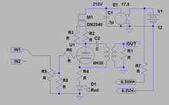
Couldn´t resist to build an preamp for the toroid poweramps. Very simple and minimalistic. The chassi is less than 5"*5"*1,5"! It will be fed by 12V and contains a 12-210V RECOM DC/DC converter(black can on top). I will try with a pair of 1,6VA Talema 115+115:18+18V toroids to get close to 5:1 in parafeed.
An externally hosted image should be here but it was not working when we last tested it.
An externally hosted image should be here but it was not working when we last tested it.
Attachments
ultrapath ...
Hi revintage,
I think you should say "ultrapath".
From Radio News Feb. 1930: “A condenser, C... ,
is needed to form a local signal circuit in the output circuit ...”
BTW: You did the same mistake Broskie did.
") att'n: The input should be cathode referred.)
att'n: The input should be cathode referred.)
Kind regards,
Darius
revintage said:You would sabotage the parafeed circuit
Hi revintage,
I think you should say "ultrapath".
From Radio News Feb. 1930: “A condenser, C... ,
is needed to form a local signal circuit in the output circuit ...”
BTW: You did the same mistake Broskie did.
att'n: The input should be cathode referred.)Kind regards,
Darius
kenpeter said:I assume you know already what happens
if you were to lift C2 halfway up into R2?
You get a balanced-current series push-pull output?
Clever.. maybe not quite 1/2 but offset by 1/Gfs...
Lars:
That's awfully cute. It would go with what I'm building
right now. I assume you'll buff the box to a nice luster.
How did you find that Recom converter? I'm using a stack
of +/-15V for B+ because I didn't know they made any HV
outputs. It's not easy to find on their website.
How do you plan to mount the converter? One method I use
is solder it to a rectangle of veroboard, etc.. larger in one
dimension and screw that down to the chassis inverted so
the converter is in contact with the chassis as a heatsink.
The little bricks like a lot of cooling.
Cheers,
Michael
#3
Hi Lars
No, of course not. It'll still be parafeed.
Kind regards,
Darius
Originally posted #3 by revintage
You would sabotage the parafeed circuit
Hi Lars
No, of course not. It'll still be parafeed.
Kind regards,
Darius
Ultrapath bypasses cathode to low impedance B+, and may have
PSRR issues with a ground referenced drive. Unless you are clever
(as oldeurope sometimes is) and drive with careful consideration
for how this problem may be turned to an advantage. He knows
some very good tricks along those lines.
But here we do not have an ultrapath to B+. We have parafeed
from a triode ref'd close to GND, and high impedance - ripple free
- constant current sink on top.
I don't see how driving common to top or bottom of cathode
resistor in this topology makes for a hill of beans either way?
Everything below the current sink is GND ref'd, and therefore
common noise.
----------------------------------------------------------------
Yes, tapping R2 halfway up will totally "Ruin Parafeed".
Don't ever try that. We don't want anything extra for free.
you should know that...
Hello Forum,
...parafeed is just the short form for parallel feed.
The opposite is serial feed.
In a serial feed (Abb.77)circuit the load in in the DC path.
 In a parallel feed (Abb.76) the load is DC free.
That's it, nothing mythical in there.
See attachment,
parallel-feed = Parallel-Speisung
serial-feed= Serien-Speisung
Kind regards,
Darius
Hello Forum,
...parafeed is just the short form for parallel feed.
The opposite is serial feed.
In a serial feed (Abb.77)circuit the load in in the DC path.
In a parallel feed (Abb.76) the load is DC free.That's it, nothing mythical in there.
See attachment,
parallel-feed = Parallel-Speisung
serial-feed= Serien-Speisung
Kind regards,
Darius
Attachments
#8
Hello kenpeter,
you are right, I had Broskie's in my mind.
To answer your question, please have a look there:
http://www.nutshellhifi.com/library/Tube_Fest_Talk.html
Lars is making something equal to the Western Electric (output).
The problem is that the current source is imperfect and the
output transformer adds an unknown impedance to the anode.
This generates a 'noise' current in the cathode resistor and adds its 'noise' voltage drop to the input.
This problem is solved by referring the input to cathode, see Western Electric (repeater amplifier).
The LED in Lars's circuit has a low impedance and makes the cathode ground referred. But what about R4?
Kind regards,
Darius
Originally #8 posted by kenpeter
...
I don't see how driving common to top or bottom of cathode
resistor in this topology makes for a hill of beans either way?
Everything below the current sink is GND ref'd, and therefore
common noise.
...
Hello kenpeter,
you are right, I had Broskie's in my mind.
To answer your question, please have a look there:
http://www.nutshellhifi.com/library/Tube_Fest_Talk.html
Lars is making something equal to the Western Electric (output).
The problem is that the current source is imperfect and the
output transformer adds an unknown impedance to the anode.
This generates a 'noise' current in the cathode resistor and adds its 'noise' voltage drop to the input.
This problem is solved by referring the input to cathode, see Western Electric (repeater amplifier).
The LED in Lars's circuit has a low impedance and makes the cathode ground referred. But what about R4?
Kind regards,
Darius
Re: #8
If the output loop included r4, would be simple degenerative
feedback. But it is outside that series resonant output loop.
Don't know what flavor or phase of noise that might add to
GND as seen by the cathode? I don't think it is noise related
to B+ ripple, if we care only from a PSRR perspective.
With Gm of only 325000uMhos, we can let it slide this time.oldeurope said:The problem is that the current source is imperfect
I honestly can't predict what r4 might do in this configuration.oldeurope said:The LED in Lars's circuit has a low impedance and makes the
cathode ground referred. But what about R4?[/B]
If the output loop included r4, would be simple degenerative
feedback. But it is outside that series resonant output loop.
Don't know what flavor or phase of noise that might add to
GND as seen by the cathode? I don't think it is noise related
to B+ ripple, if we care only from a PSRR perspective.
Add a bypass cap from anode to GND? What you have left is
a cathode follower, with no "4th circuit" input at the plate,
and slightly less than unity gain. This is not the same circuit
anymore, not sure what it reveals about the R4 question?
I do not think R4 faithfully follows the grid in the original.
As it is modulated by load and parafeed reactance at the
plate input/output of the Triode. Outside the loop of the
output circuit, I can't be sure the phase shift seen by R4
to be entirely negative feedback or slightly something else...
Down here, below the hard power supply rejection of M1+R2,
I don't think the issue with R4 is PSRR related. It might be
one of damping factor??? Is that what you are driving at?
Hello kenpeter,
hello forum
there is a cap from anode to ground.
You can not see it, because it is not shown in the schematic.
But I am sorry you can not ignore it, even if you try.
The constant current source and the output transformer adds
a capacitor from anode to ground. In an audio transformer
you have stray capacitance between primary and secondary.
This generates an undefined impedance from primary to secondary.
A "floating ultrapath" is something people are dreaming of ...
Kind regards,
Darius
BTW: Please don't call a "floating ultrapath" a "parafeed"
thanks.
hello forum
there is a cap from anode to ground.
You can not see it, because it is not shown in the schematic.But I am sorry you can not ignore it, even if you try.
The constant current source and the output transformer adds
a capacitor from anode to ground. In an audio transformer
you have stray capacitance between primary and secondary.
This generates an undefined impedance from primary to secondary.
A "floating ultrapath" is something people are dreaming of ...
Kind regards,
Darius
BTW: Please don't call a "floating ultrapath" a "parafeed"
thanks.
Sadly, I really thought he was onto something till that last doozie.
And he was right about the cathode reference being the better.
Bending my warped mind around the surreal reason just given, I
just can't do it.... Totally off the hook and into the swimming pool.
There is a 30pF max capacitance to B+ (not ground) thru the CCS.
And the typ number is closer to 12pf. Self capacitance of windings
is not to GND. There may be a leakage capacitance to GND, and
a leakage inductance to who knows what else, but neither of any
special significance to create an alternate low impedance path for
the anode.
Windmills indeed.
Who are you?
I am the new Number Two.
Which side are you on?
That would be telling...
Who is Number One?
You are No.6.
I am not a number!
I am a floating Ultrapath!
kenpeter said:Connected across all taps? Or with free ends flying?
I can do the same with an Edcor, here in just a sec.
See #14
connected across primary and secondary of course.
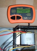
2480pF. all primaries vs all secondaries. Edcor CXPP10-MS-5K
No idea what KHz of the test? Used a Beckman Wavetek 27XT.
And exactly the same when measured from just one end of
the primary (other leads flying) to any tap of the secondary.
And about 80pf from either primary or secondary to an end
bell screw.
No idea what KHz of the test? Used a Beckman Wavetek 27XT.
And exactly the same when measured from just one end of
the primary (other leads flying) to any tap of the secondary.
And about 80pf from either primary or secondary to an end
bell screw.
- Status
- This old topic is closed. If you want to reopen this topic, contact a moderator using the "Report Post" button.
- Home
- Amplifiers
- Tubes / Valves
- Building PRETOR toroid preamp